for RoGator
Boom Sensor Mounting Locations
Sensor mounting locations vary by boom configuration. If an object enters the sensor’s blind range unexpectedly, a false return to the sensor could occur. To ensure optimal operation of the AutoBoom® XRT system and to protect the sprayer boom, the sensor should be mounted behind the boom structure (if possible), above the lowest hanging part of the boom.
Mount the Boom Sensors
|
|
|
|---|---|
|
|
The implement or machine must remain stationary and switched off with booms or implement sections unfolded and supported during installation or maintenance. |
 warning
-
The table below provides the approximate mounting locations for various boom widths. The information on this table is for reference only. If there is interference or other issues with these mounting locations, mount the sensors as close to these locations as possible.
Boom Width Boom Type Inner Sensor Mounting Distance from Boom Pivot Point Outer Sensor Mounting Distance from Boom Pivot Point 120' Steel 322" 660" 100' Steel 290" 495" 90 Steel 290" 435" Note: The numbers in the table above are the approximate distance. As a rule, the sensor should be mounted half way between two spray tips to minimize potential drift interference.
-
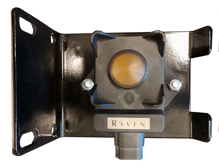
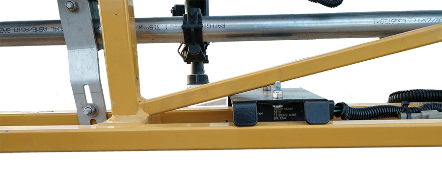
Install the radar sensors (P/N 063-0173-962) on the sensor mounting brackets (P/N 107-0235-032) using two 1/4”-20 x 5/8” Phillips pan head bolts (P/N 311-0050-255) and two 1/4”-20 nylon locking nuts per sensor (P/N 312-4000-164).
Note: Install two of the sensors in one orientation and three in the other orientation on the bracket so, when installed, the sensor connection is facing towards the center of the machine.
-
Mount the boom sensor assemblies on the back of the left-outer boom sections using 1-9/16” W x 2-1/2” L x 3/8” thread U-bolts and 3/8”-16 flanged lock nuts.
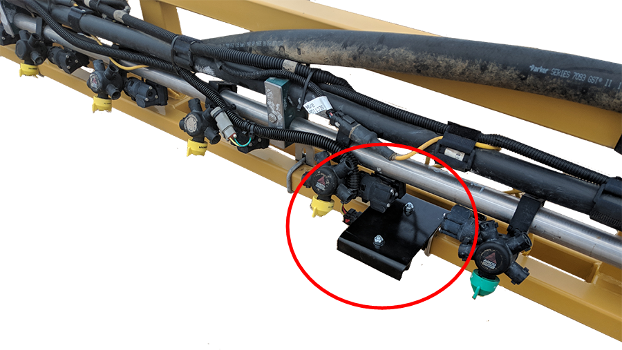
Note: The radar sensor will be mounted on the rear of the boom. Verify that the radar bracket does not hit inner boom when folding booms.
-
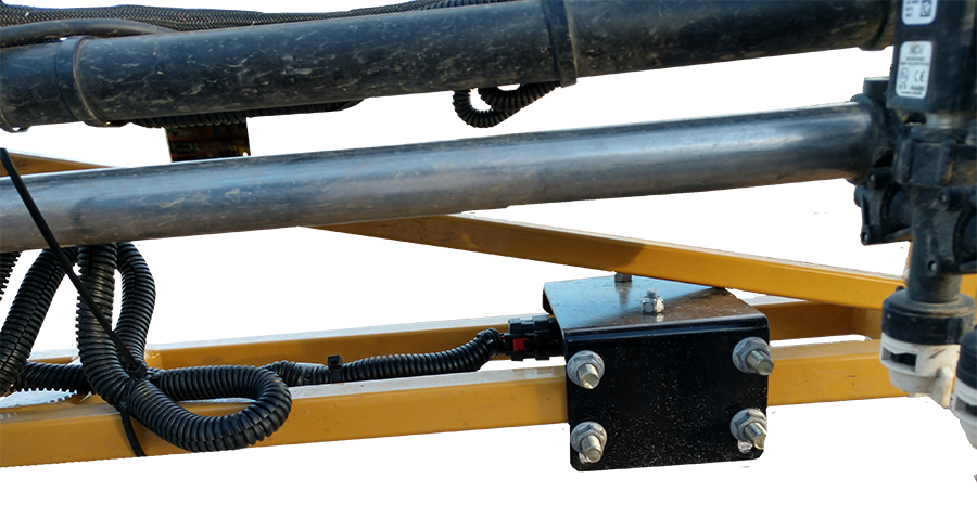
Mount the inner boom sensor assemblies using 1-9/16” W x 2-1/2” L x 3/8” thread U-bolts and 3/8”-16 flanged lock nuts.
Mount the Center Sensor
-
Mount the center sensor assembly to the middle of the center rack using 1-9/16” W x 2-1/2” L x 3/8” thread U-bolts and 3/8”-16 flanged lock nuts. The center sensor may be offset from center due to the structure of the center rack.
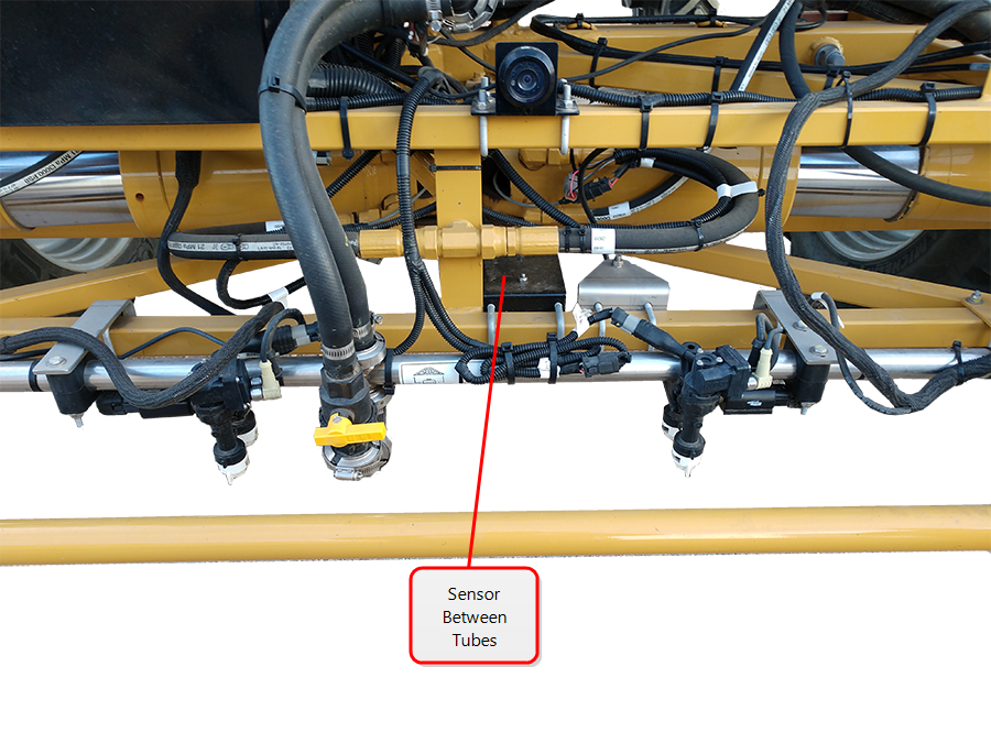
Note: The center sensor can be moved off-center to be located directly above a row for better crop-detection performance.
Last Revised: Jul 2024