for RoGator C
Note: While making the following connections, be aware of the cable routing and avoid cable pinch points and other issues.
-
Insert the gray 23-pin plug on the ABM/REM
 Raven Expansion Module cable (P/N 115-0235-109) to the mating connector on the bottom of the REM node.
 -
Insert the black 23-pin plug on the AutoBoom® XRT cable to the mating connector on the bottom of the REM node.
-
Insert the black 35-pin plug on the AutoBoom® XRT cable to the mating connector on the bottom of the REM node.
-
Insert the connector labeled ABM to the AutoBoom® XRT node.
-
Use the provided 12-pin green DTM plug to protect the unused connector of the ABM node.
-
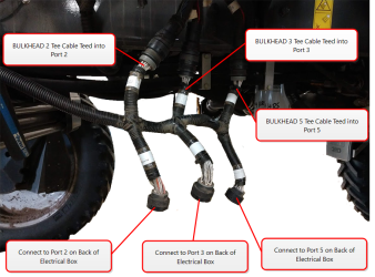
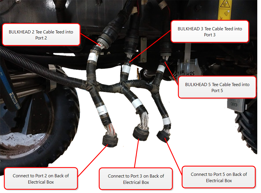
Disconnect the Bulkhead Connector 2 from port 2 on the back of the electrical box and connect it to the BULKHEAD 2 ABM/REM Tee cable.
-
Connect the other end of the bulkhead 2 tee back into port 2 on the back of the electrical box.
-
Disconnect the Bulkhead Connector 3 from port 3 on the back of the electrical box and connect it to the BULKHEAD 3 Tee on the ABM/REM cable.
-
Connect the other end of the bulkhead 3 tee back into port 3 on the back of the electrical box.
-
Disconnect the Bulkhead Connector 5 from port 5 on the back of the electrical box.
-
Remove the nut securing the bulkhead 5 plug to the electrical box.
-
Access the inside of the electrical box and locate the bulkhead 5 plug.
-
Install the Chassis Adapter cable (P/N 115-0235-108) bulkhead plug into the open location on the back of the electrical box and secure with a nut.
-
Connect the other end of the bulkhead 5 tee back into the plug now in port 5 on the back of the electrical box.
-
Plug the machines bulkhead 5 connector into the mating connector on the Chassis Adapter cable.
-
Install the ground and power ring terminals to the power and grounds studs on the right wall of the electrical box.
-
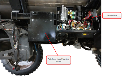
Locate the electrical box on the right side of the machine by the rear tire. Locate the C180 RVN POWER CONNECTOR on the inside of the electrical box.
-
If there isn’t a cable connected to the C180 connector, plug the end into the LOGIC/POWER TEE connector on the chassis adapter cable.
-
If there is a cable connected to the C180 connector, disconnect the existing cable and install the LOGIC/POWER TEE cable into the C180 cable. Connect the plug that was originally in the C180 cable to the open receptacle on the LOGIC/POWER TEE cable.
-
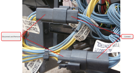
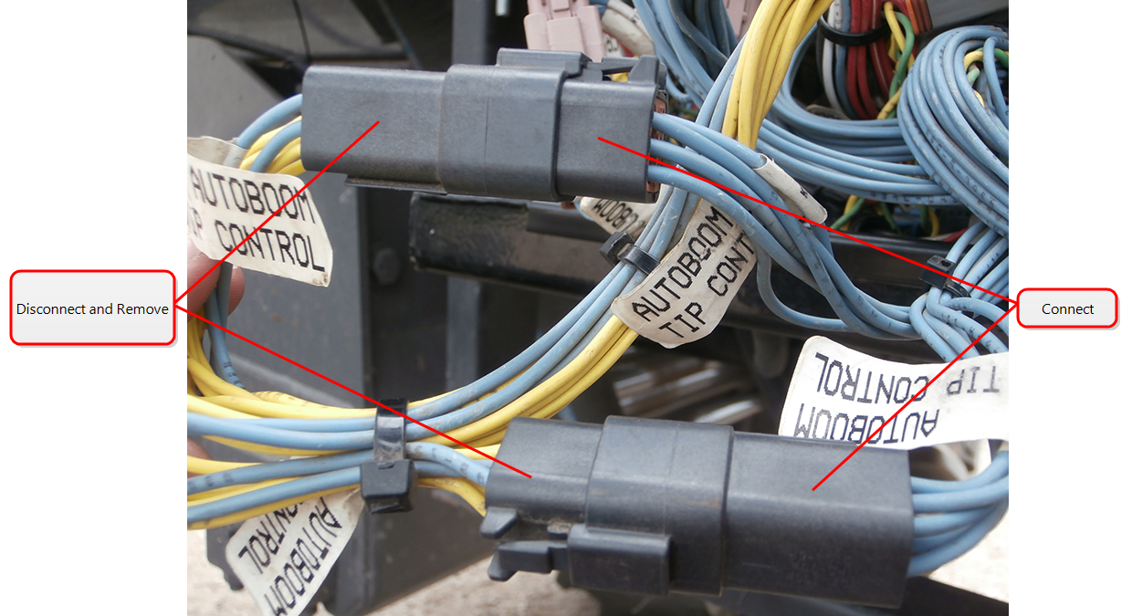
If an AutoBoom® UltraGlide system has been installed at the factory, unplug and remove the 6-pin connector with blue and yellow wires connected to the UltraGlide node. Reconnect the remaining connectors with blue wires together to complete the circuit.
-
-
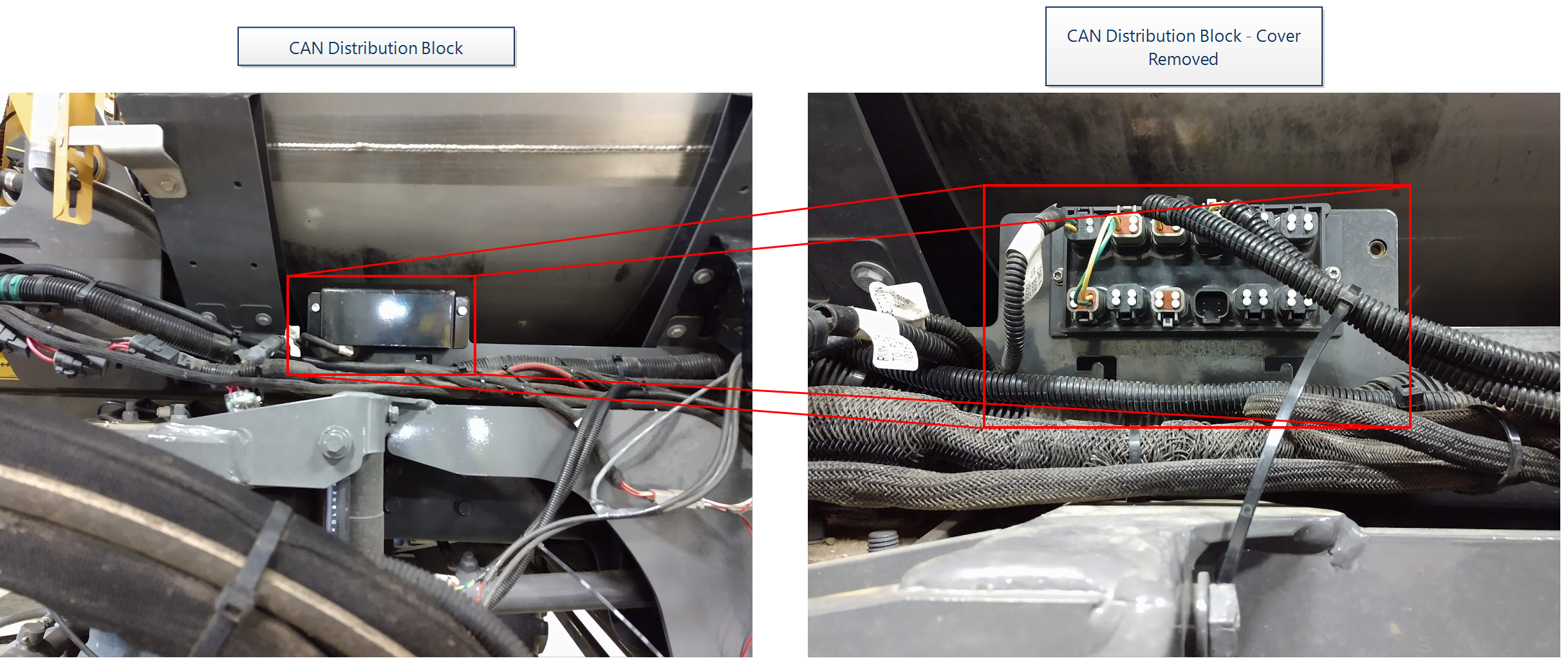
Remove the cover from the CAN distribution block.

-
Plug the 4-pin connectors on the AutoBoom® XRT cable to any available ports on the top row of the CAN distribution block.
-
Reinstall the CAN distribution block cover.
-
Install the RESISTOR BLOCK cable (P/N 115-0235-118) to the 6-pin plug on the AutoBoom® XRT cable.
-
Locate the RoGator C Valve cable (P/N 115-0235-112).
-
Connect the plug labeled DAMPER 1 to the mating receptacle on the right damper.
-
Connect the plug labeled DAMPER 2 to the mating receptacle on the left damper.
-
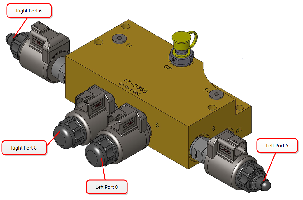
Connect the LEFT SOLENOID plug on the AutoBoom® XRT cable to the left port 8 on the AutoBoom® XRT valve.

-
Connect the RIGHT SOLENOID plug on the AutoBoom® XRT cable to the right port 8 on the AutoBoom® XRT valve.
-
Connect the LEFT PROP plug on the AutoBoom® XRT cable to left port 6 on the AutoBoom® XRT valve.
-
Connect the RIGHT PROP plug on the AutoBoom® XRT cable to right port 6 on the AutoBoom® XRT valve.
-
Connect the 12-pin receptacle on the valve harness to the existing machine plug labeled X5033 behind the valve.
Note: The ACCUMILATOR POWER connector is not used on this installation.
-
Reinstall the cover on the electrical box.

Last Revised: Jul 2024