AutoBoom® ECU (ABM) Specifications
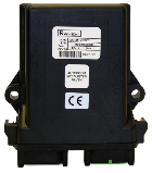
(P/N 063-0174-066)
Mounting Location
Mounting location is on the machine chassis:
-
Mount ABM on chassis frame.
-
Mount with connectors in the down position.
-
Must mount rigid with limited vibration.
-
Overall Dimensions: 4.70 x 5.26 (in.)
Protection
Must provide protection for the ABM cabling:
-
Cable must be routed away from pinch points.
-
Cable must be routed to prevent damage.
-
Cable must be properly secured to avoid interference.
Connector Specifications
| J1 Gray 12-Pin DTM | ||
|---|---|---|
| Pin | Description | Color |
| 1 | ||
| 2 | ||
| 3 | LOGIC PWR | Red |
| 4 | ||
| 5 | ABM SUBNET CAN HI | Yellow |
| 6 | ISO CAN HI | Yellow |
| 7 | ISO CAN LO | Green |
| 8 | ABM SUBNET CAN LO | Green |
| 9 | ||
| 10 | LOGIC GND | Black |
| 11 | ||
| 12 | ||
ABM Connector Pinout:
-
Supply Voltage: 8-36 VDC
-
Current: 60 mA
-
ISO11783 CAN Protocol
-
IP rating: IP67
-
Deutsch DTM 12-pin
-
GRAY: DTM06-12SA
-
GREEN: DTM06-12SC
-
Last Revised: Jul 2024