Radar Specifications
(Boom Height Sensor; P/N 063-0173-962)
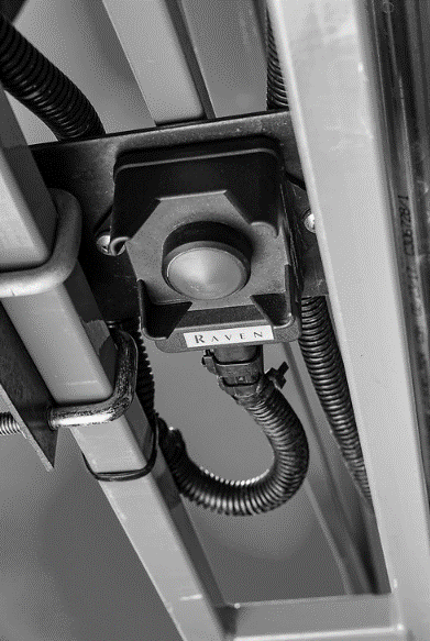
Mounting Location
Ideal mounting location is within the structure of the boom in front of the spray nozzles:
-
Mount Radar bracket midway between spray nozzles.
-
Mount outer sensor approximately 39” (1m) from the end of the boom.
-
Mount Intermediate Radar on primary section of boom.
-
Mount with connector directed toward center of machine.
-
Mounting on Center Rack is required.
-
Ensure brackets do not interfere with spray nozzles with folding of booms.
-
Mounting bolts: M6 size.
Mounting Angle
-
Angle: 90°±1°.
-
Measured with the machine level, in relation to the radar and the ground.
Field of View
-
From the sensor, a 70° cone (from the base of the sensor) should be clear of obstructions (except the ground).
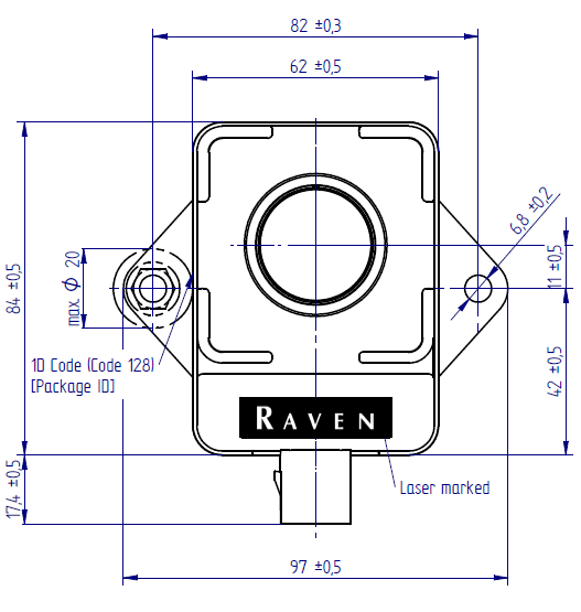
Sensor Dimensions

-
The sensor is 0.45 in. [11.43 mm] above the base plate as seen in the image above and the cone follows the contours of the sensor enclosure body.
-
Dimensions of the sensor (mm).
Protection
Must provide protection for the sensor:
-
Cable must be routed away from pinch points.
-
Cable must be routed to prevent damage.
-
Cable must be properly secured to avoid inerference.
Connector Specifications
| Mating Connector AMPSEAL 16 | |
|---|---|
| 776524-1 | |
| Pin 1 | +Vs |
| Pin 2 | CAN HI |
| Pin 3 | GND |
| Pin 4 | CAN LO |
Radar Connector Pinout:
-
Supply Voltage: 9-16 VDC
-
Current: <160 mA each
-
IP Rating: IP69K
-
Ampseal 16: 776524-1
Last Revised: Jul 2024