Wheel Control Settings (Machine Steering Only)
Note: Some pages and options may differ based upon how the machine or implement is configured.
-
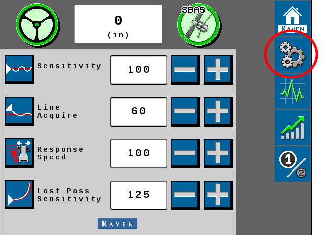
From the auto-steer Home page, select the Tools
 button.
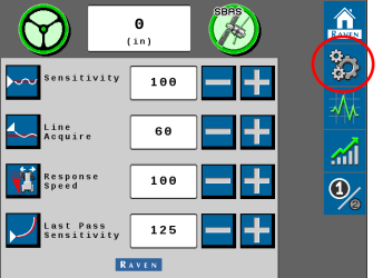
-
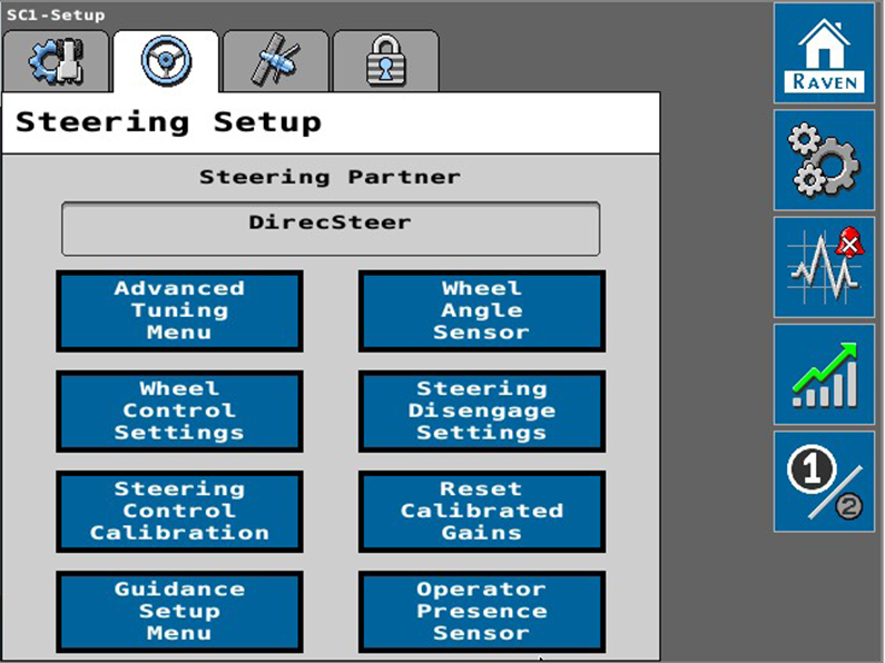
Select the Steering Setup
 tab.
tab.
- Select the Wheel Control Settings button.

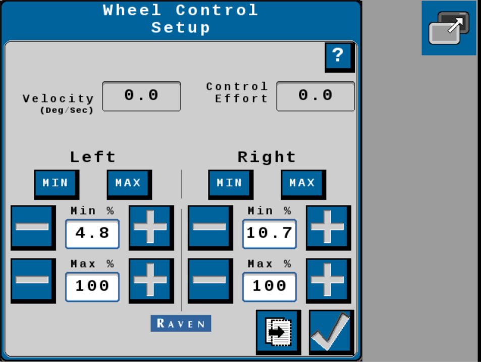
Informational Readouts
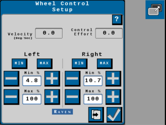
The Wheel Control Setup page displays the following information:
Note: Select the Help Menu ![]() icon to access the Help Menu. The Help Menu may contain additional information about the features and options displayed on the page.
icon to access the Help Menu. The Help Menu may contain additional information about the features and options displayed on the page.
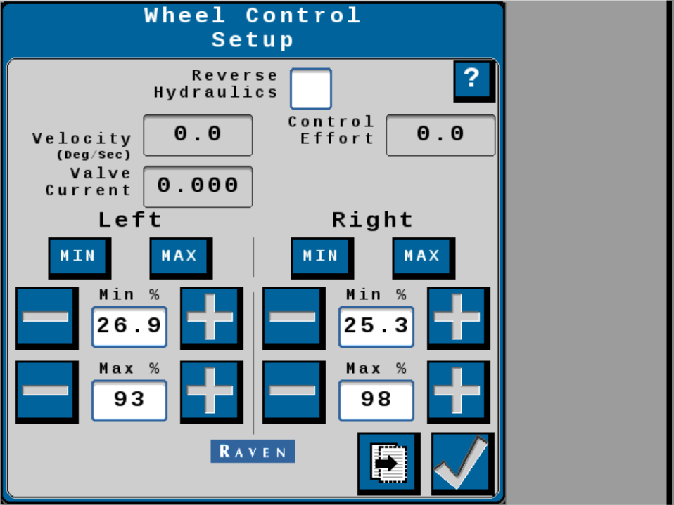
Velocity or Wheel Velocity
The speed at which the wheels are moving, measured in degrees per second.The speed at which the implement steering actuator is moving, measured in voltage per second.
Control Effort
The amount of effort the system is using to drive the wheels.The amount of effort the SC1™ system is using to drive the implement steering actuator.
Motor or Valve Current
Displays the current (amps) draw of the steering valve or motor.
Reverse Hydraulics
Enable this option if control inputs have the opposite effect on the steering axle or implement actuator. For example, when turning the steering wheel to the left moves the wheels right.
Min and Max Buttons
Touch and hold the MIN or MAX button to test the steering system response. The auto-steer system will use the set minimum and maximum percent values to drive the steering axle or actuators to the left or right (narrow or widen for plough applications).
For example, hold the Left MIN button to steer the machine to the left using the minimum control effort percent.
Minimum Percent
Set the Min % to the minimum value required to move the steering axle or implement steering actuator. Values range from 0 - 99.
Note: Left and right values may be set independently. The Min values cannot exceed the Max values.
Maximum Percent
The Max % value may be used to limit the control effort which auto-steer system may use to steer the axle or implement steering actuator. Values range from 1 - 100.
Note: Left and right values may be set independently.
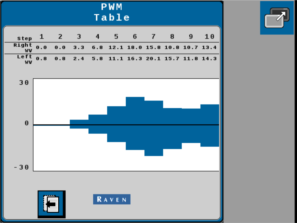
PWM Table
From the Wheel Control Setup page, select the Next button to review the PWM Table![]() A group of intersecting columns and rows that you can add to a topic for various purposes, such as comparing one thing with another or giving field descriptions for a software dialog. page for the last completed calibration. The PWM table displays the control effort for various target angles.
A group of intersecting columns and rows that you can add to a topic for various purposes, such as comparing one thing with another or giving field descriptions for a software dialog. page for the last completed calibration. The PWM table displays the control effort for various target angles.
Last Revised: Jul 2024