Connect Combine OMNiDRIVE™ System Cables
Note: During the installation process, note the serial number and bar code of the following devices and the machine on which each device is installed:
- Slingshot®Field Hub
- RS Lite
- CR7™
This information will be required during device registration and field provisioning procedures and will help locate each device within the Slingshot® portal.
Note: Please allow up to 4 business days to activate the Field Hub. Once activation has been completed, a confirmation email will be sent to the customer and an OTA![]() (Over the Air) Software updates and other information pushed from Slingshot® servers via the Slingshot® system. software update will be pushed to the Field Hub the next time the device powers up. It may be recommended to complete and submit the OLAF
(Over the Air) Software updates and other information pushed from Slingshot® servers via the Slingshot® system. software update will be pushed to the Field Hub the next time the device powers up. It may be recommended to complete and submit the OLAF![]() Online Activation Form procedures for the Field Hub on all OMNiDRIVE™ machines. Refer to the following for additional assistance:
Online Activation Form procedures for the Field Hub on all OMNiDRIVE™ machines. Refer to the following for additional assistance:
OMNiDRIVE™ System Diagram - Combine
Roof Connections
RS Lite and Trimble 372 Connections Radio and Power Connections for Kit
- Locate the 12-pin plug labeled RS Lite on the RS Lite to 372 cable (P/N 115-2610-114) and connect to the port on the RS Lite.

-
Route the Trimble 372 branch to the Trimble 372 receiver at the rear of the cab roof.
- Connect the 8-pin plug labeled Radio to the battery to roof cable (P/N 115-2610-059) or (P/N 115-2610-051).
- If using cell RTK
 Real-time Kinematic, connect the 12-pin plug on (P/N 115-2610-115) cable to the plug labeled RTK on cable (P/N 115-2610-114).
 - The other end of the cable will connect to the Slingshot® modem.
Radio and Power Connections
- On the battery to roof cable (P/N 115-2610-051 or 115-2610-059), route and connect the small, round connector to the radio mounted to the roof bracket.
Note: For kit (P/N 117-2610-018) the only roof cable option is (P/N 115-2610-059).
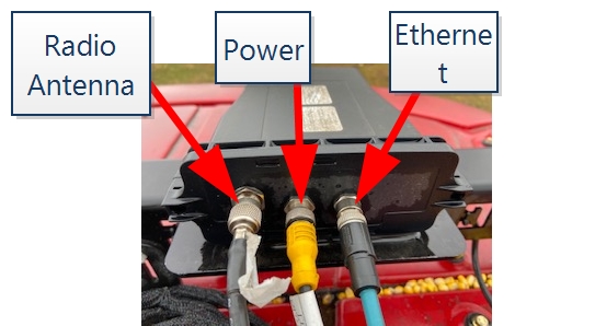
- Locate the free end of the radio cable (P/N 115-2610-023) and connect it to the radio.
Ethernet Cables and Routing to Cab Pass-Through
- Connect the Ethernet cable (P/N 420-2002-089) to the RS Lite.
- Connect the Ethernet cable (P/N 420-2002-091) to the radio.
Note: The other end of these Ethernet cables will be routed through the cab pass-through. It is recommended to use a marker to label the cab end of the Ethernet cable to simplify connections later.
- Locate the following cables previously connected or installed to OMNiDRIVE™ system components on the combine roof:
- E-Stop Emergency stop button or switch. cable (P/N 115-2610-056) previously connected to the E-Stop antenna on the antenna bracket.
- Ethernet cables from the RS Lite and radio.
- Open connectors on the battery to roof cable (P/N 115-2610-051 or 115-2610-059). For kit (P/N 117-2610-0189) the only roof cable option is (P/N 115-2610-059).
- RTK cable (P/N 115-2610-115) from the roof cable to the Slingshot® modem if used.
Route these plugs through the cab pass-through.

- E-Stop
- Group and secure cables routed from the roof to the pass-through as needed. Review Recommendations and Best Practices for additional information on cable routing.
In-Cab Connections
RS Lite and Radio Ethernet Connections
- Route the Ethernet cable previously connected to the radio to the port labeled X1 on the Ethernet switch.
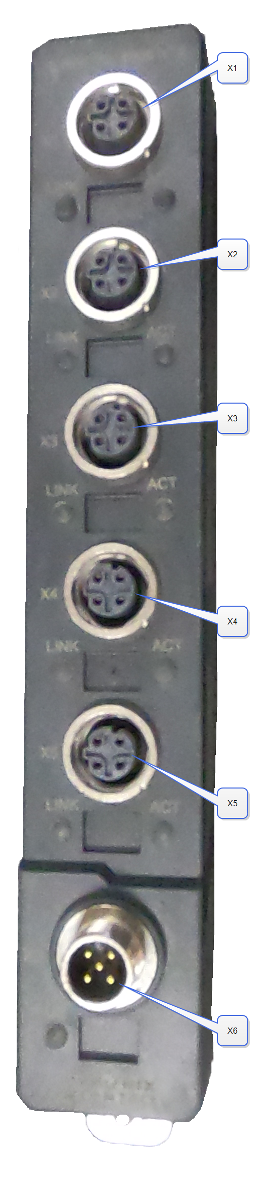
- Route the Ethernet cable previously connected to the RS Lite to the port labeled X2 on the Ethernet switch.
Complete CR7™ and E-Stop Connections
- Route the E-Stop cable from the antenna bracket on the roof to top port on the E-Stop mounted with the CR7™ field computer.
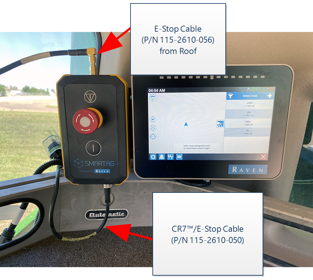
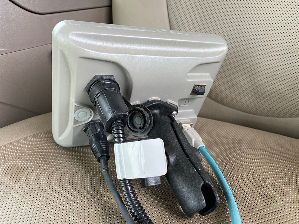
- Connect the two round plugs on the CR7™/E-Stop cable to the back of the CR7™.
- Route the small, round plug to the bottom port of the E-Stop.
- Connect the 8-pin plug to the 8-pin connector on the battery to roof cable routed from the roof (P/N 115-2610-051).
Note: The 2-pin plug labeled Aux Power is not used during installation.
- Connect the Ethernet cable (P/N 420-2002-081) to the back of the CR7™ field computer.
- Route the Ethernet cable to the port labeled X4 on the Ethernet switch.
Tablet and Field Hub Connections
- Connect the tablet charger cable (P/N 420-1011-013) to the power port on the tablet.
- Connect the charger cable to the tee power cable (P/N 115-2610-084) using the adapter power cable (P/N 115-2610-085).
- Locate the 2-pin plug on the battery to roof cable from the roof and insert the mating connector from the tee power cable.
- Connect the combine power cable (P/N 115-2610-065) to the remaining connector on the tablet tee power cable.
- Route the square, 4-pin plug on the combine power cable to the power port on the Slingshot® Field Hub.
- Connect the serial connector on the RTK cable (P/N 115-2610-115) to the corresponding port on the Slingshot® Field Hub if used.
- Connect the round, 4-pin plug on to the port labeled X6 on the Ethernet switch.
- Connect the tablet Ethernet cable (P/N 420-2002-081) to the Ethernet port on the tablet.
- Route the Ethernet cable to the port labeled X5 on the Ethernet switch.
Power Connection
- Connect the battery to roof cable to the auxiliary power adapter strip located to the right of the operator seat.

Note: For other makes/models, locate a source within the cab that will supply +12 V constant power, +12 V key switch power, and a ground.
- The OMNiDRIVE™ system should now be installed on the combine. Review the Installation Overview to confirm all procedures have been completed.
Last Revised: Jul 2024