Provision the GPS Receiver
Configure the Trimble® Receiver
Note: The following settings are made through the AFS® Pro700 or Trimble AgRemote™ software. The screenshots appearance will vary depending on which application is used.
-
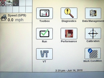
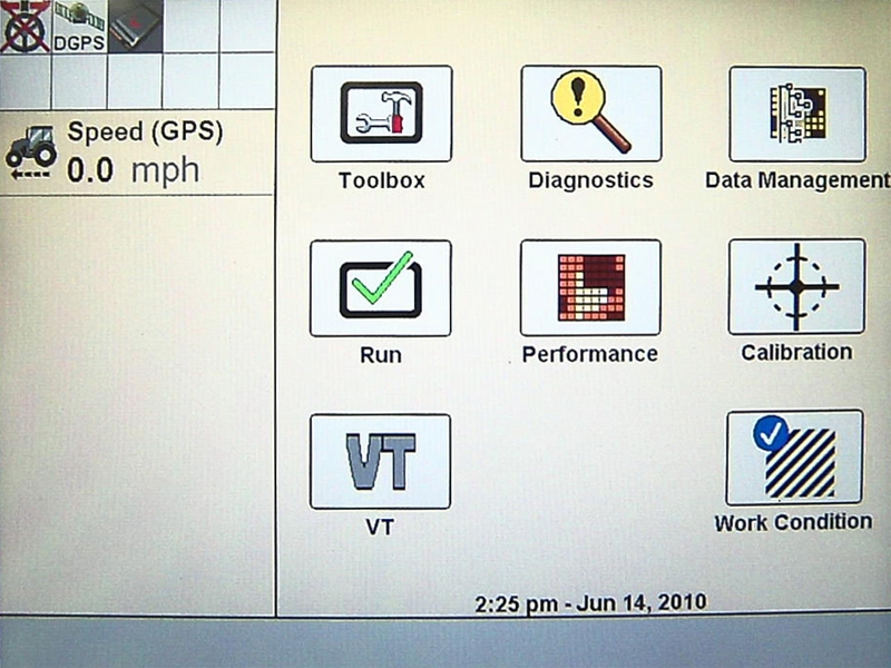
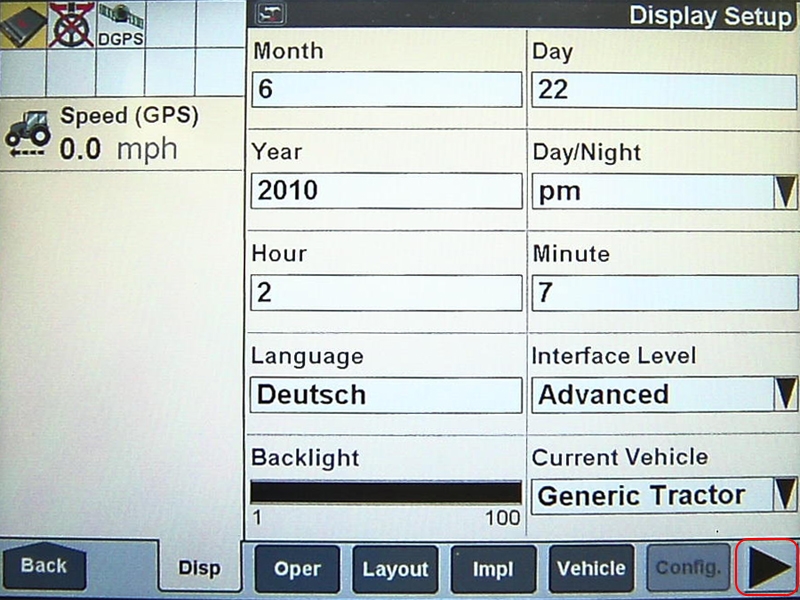
From the AFS Pro700 main menu select Toolbox.
-
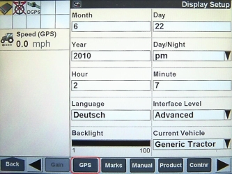
The Display Setup Screen will open.

-
Select
 .
. -
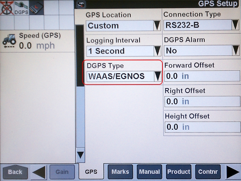
Select GPS.
-
Select the DGPS
 Differential Global Positioning System is an enhancement to standard GNSS/GPS messages to provide better position accuracy. Type drop-down box.
-
Select RTK
Real-time Kinematic.
-
Verify that the Chanel ID field displays No Radio and that the RTK/RTX Source is set to AgGPS Radio.

-
Press the Back button on the GPS Setup screen.
-
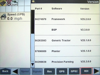
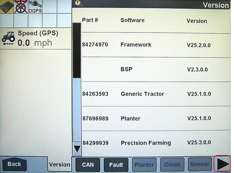
Select Diagnostics.

-
Select
.
-
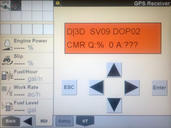
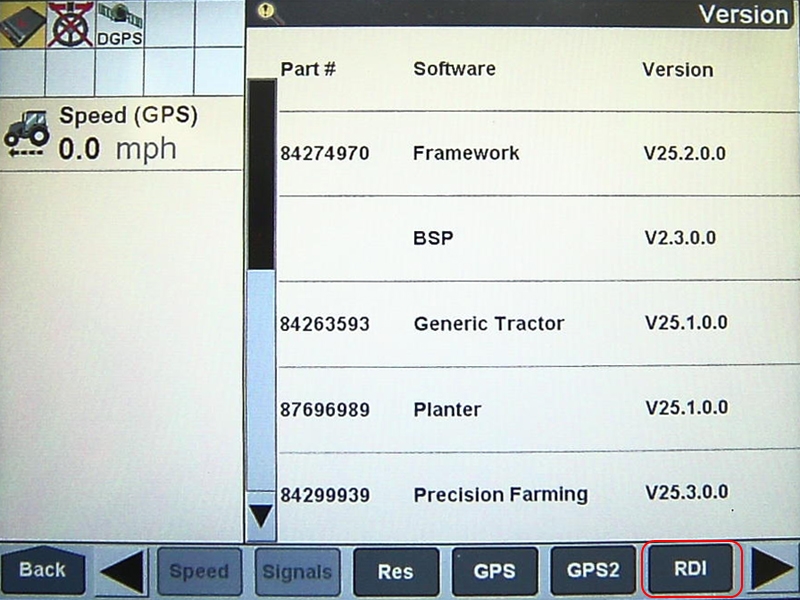
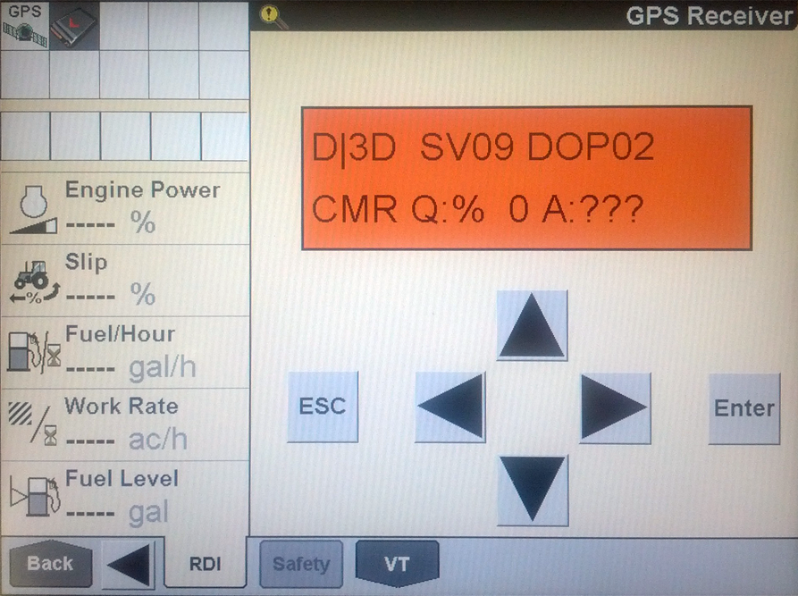
Select RDI. The following screen will appear.
NOTICE
The settings contained in the text below have been thoroughly tested and verified. The change in settings resulted in improved RTK availability in real field conditions when used with the Slingshot® system. However, Raven Industries in no way guarantees or warranties the equipment configuration of non-Raven equipment. Please contact your Trimble customer support for further details.
To ensure optimal RTK signal availability with the AgGPS 262/AG-372 receiver, it may be necessary to adjust the DOP mask settings. While a low RTK DOP mask setting provides high confidence in GPS position, GPS constellation settings often drop RTK fix in some geographic regions.
Trimble provides a DOP predictor tool that assists in determining acceptable settings for specific geographical areas. Adjust the receiver settings as indicated below to change the "to fix" and "when fixed" conditions.
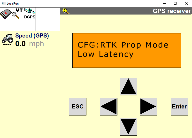
If the settings do not match what is shown, toggle through the options until the settings change to match the settings shown. To change the settings.
-
Press the
until the item to be changed flashes. -
Select the
 or
or  button to change the setting.
 -
Select Enter.
-
-
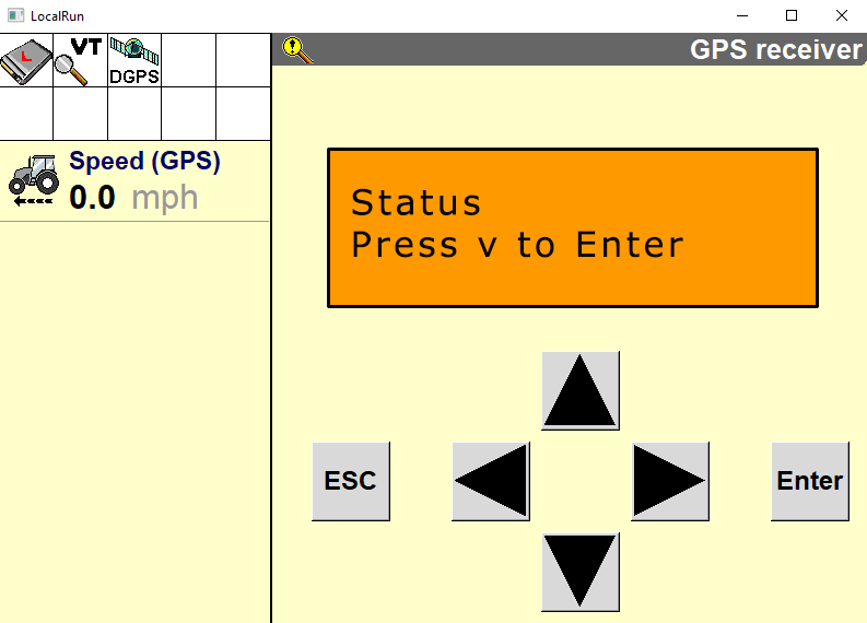
Select
. The following screen will appear:
-
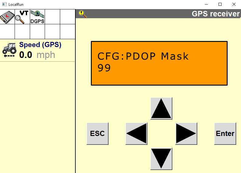
Select
. The following screen will appear:
-
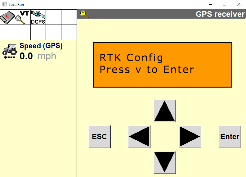
Select
. The following screen will appear:
-
Select
. The following screen will appear: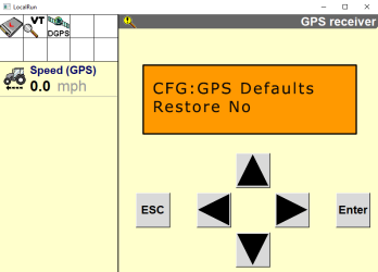
-
Select
. The following screen will appear.
-
Select
. The following screen will appear (AG-372 Only):
-
Select
. The following screen will appear: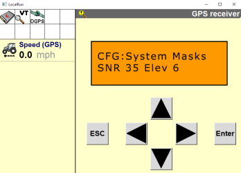
Note: A lower Elevation Mask setting offers a better view of satellites, which can improve RTK availability.
-
Select
. The following screen will appear:
-
Select
. One of the following screens will appear depending on which receiver is installed: -
Select ESC. When the GPS Config screen reappears, select
. The following screen will appear:
-
Select
. The following screen will appear:
-
Select ESC. The following screen will reappear:
-
Select
. The following screen will appear.
-
Select
. The following screen will appear:
-
Select
. The following screen will appear: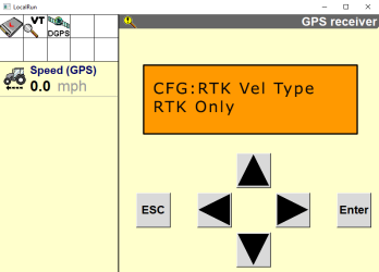
-
Select
. The following screen will appear:
Note: Selecting the Favor Avail setting will result in improved RTK availability.
-
Select
. One of the following screens will appear depending on which receiver is installed: -
Select
. The following screen will appear:
-
Select
. The following screen will appear:
-
Select
. The following screen will appear:
-
Select
. The following screen will appear:
-
Select
. The following screen will appear:
-
Select ESC.


Port A Configuration
-
Press the right button until "Configuration" displays on the screen.
-
Press the down button to select "Configuration".
-
Press the right button until "Port A Config" displays.
-
Press the down button to select "Port A Config".
-
Ensure the input (I) messages are set to CMR and the baud rate is set to 115K.
-
Verify the Output (O) messages are set to 8N1 and that the NEMA and baud rates are set to 115K.

-
Press Enter to save the settings.
-
Press the Down button until NEMA1 displays.
-
Verify that GGA and GSA are capitalized so they are on.

-
Press Enter to save the settings.
-
Press the Down button until NEMA2 displays.
-
Verify that VTG and ZDA are capitalized so they are turned on.

-
Press the down button to continue configuring Port A.
-
Press the down button until CFG: Port A Out RTS_CTS displays.
-
Verify CFG: Port A Out RTS_CTS is off.

-
Press Enter to save the settings.
-
Press the Down button to continue configuring Port A.
-
Press Enter to save the settings.
-
Press the Down button until NEMA out displays.
-
Ensure that NEMA out and TSIP out are set to ASAP. This will require arrowing over a second time once the "s" field is underlined.

-
Press Enter to save the settings.
-
Press the Down button until CFG: NEMA Quality displays.
-
Verify the setting is Report True Mode.

-
Press Enter to save the settings.
-
Repeat these steps to configure Ports B and C.


Confirm GPS Setup
-
Select the ISOBUS button to bring up the object pool
The user interface for a system or feature connected to an ISOBUS UT.. 
-
Select the RS Lite UT
A Universal Terminal (formerly Virtual Terminal) is an electronic display or console capable of interfacing with ECUs on an ISOBUS network. working set The user interface for a system or feature connected to an ISOBUS UT..
-
Select the Settings
 button on the right side of the screen.
-
Select the GPS Setup Button at the top of the screen.

-
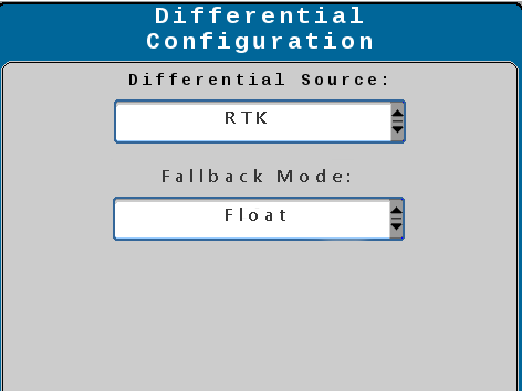
Select the Differential
Differential Global Positioning System is an enhancement to standard GNSS/GPS messages to provide better position accuracy. Configuration Setup button. -
RTK and Float should be shown.
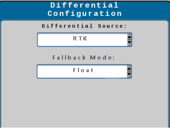
-
Select the check mark button.
-
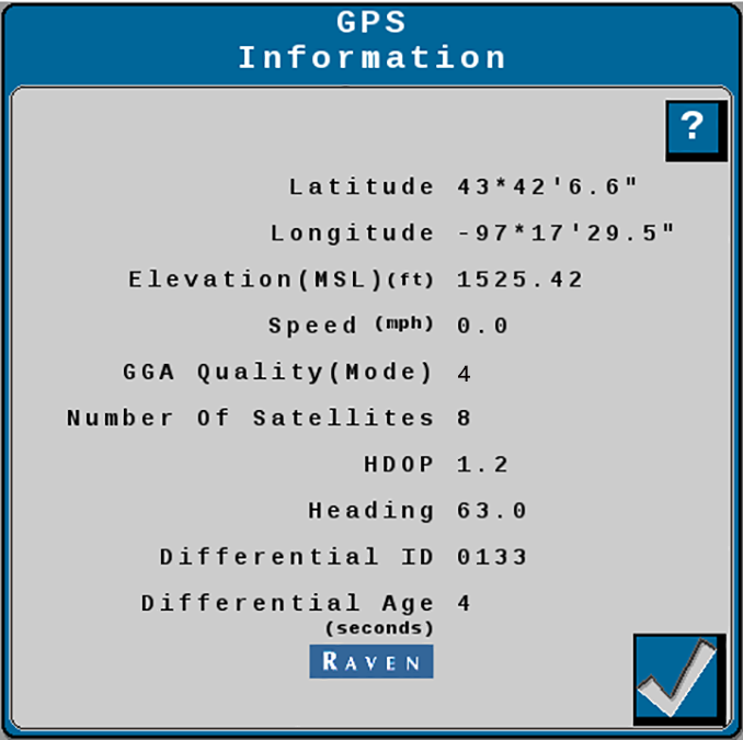
Select GPS Information button.

-
A 4 should be displayed in the GGA Quality (Mode) section in the center of the screen.


Last Revised: Nov 2023