First Time Calibration
Note: Depending upon configuration settings and installed unlocks, the following steps may vary.
After installing the AutoBoom® XRT system:
-
Park the machine on a level surface.
-
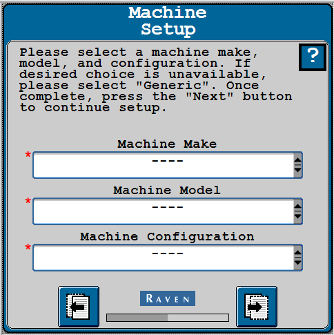
Select the Machine Make, Machine Model, and Machine Configuration.
-
Select Next.
-
Verify the number of height sensors installed on the booms and center rack. This will be three, five, or seven sensors depending upon the number of sensors installed.
Note: If there are no Height Sensors Detected, select Refresh
to re-detect the number of sensors.
-
Select Next.
Note: If the AutoFold feature is unlocked, AutoFold will be calibrated at this time. Refer to AutoFold Calibration for assistance with calibrating the AutoFold system. Once the AutoFold calibration is complete, proceed with the following steps to continue the AutoBoom® XRT calibration.
-
Verify the orientation of the ABM (ECU
 Electronic Control Unit) on the machine matches the downward/forward orientation of the controller on the page.
 Note: Many of the next screens will populate with default settings based on the machine configuration selected earlier. The settings will need to be changed if the actual installation deviated from the directions in the machine-specific installation manual.
-
If required, press the Redetect Orientation button to redetect the orientation of the ABM on the Downward Orientation page.
Note: The downward and forward orientations can be entered in the appropriate fields.
-
Verify the machine is parked on a level surface.
-
Select Calibrate Terrain Compensation.
-
After terrain calibration compensation is complete, select Next.
Note: If the AutoFold feature is unlocked and already calibrated, the following steps will have been completed during the AutoFold calibration.
-
Fold the boom in so the booms are stored in the transport position.
-
Select the Next button to continue fold calibration.
-
If AutoFold is unlocked, raise the booms above the cradle lip and inward to contact vertical stops. Booms will control to the set point when cradling.
-
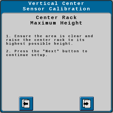
If the next screen reads Center Rack Maximum Height, complete the steps in the following drop-down. If not, continue to the next step.
 Set Center Rack Maximum Height
-
Raise the center rack to the maximum height.
-
Select the Next button to continue the fold calibration.
-
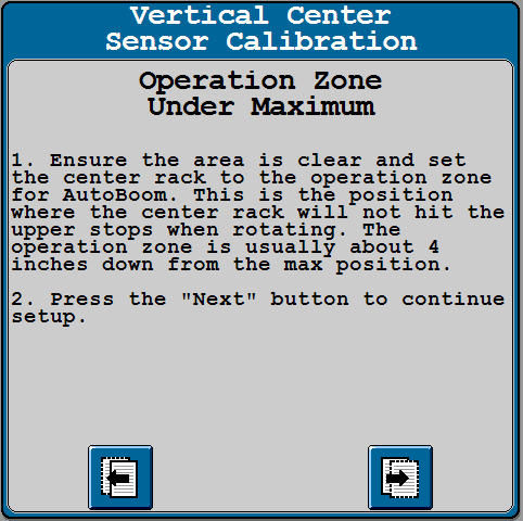
Unfold the inner booms and lower the center rack to the operating position if required.
Note: For AGCO RoGator machines, this is low enough that the center rack is able to rotate freely without hitting the travel stops. This is typically about 4 in. [10 cm] below the maximum center rack height.
-
Select the Next button to continue the fold calibration.
-
-
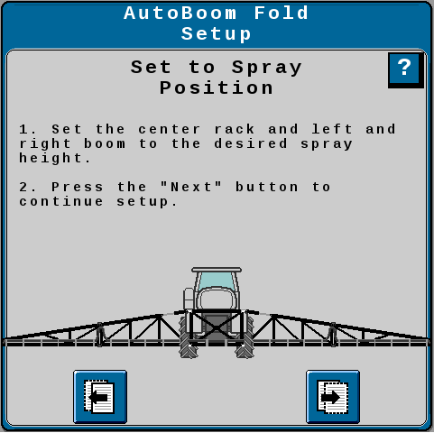
Move the booms to a typical spray position. The center rack should be well below the travel stops and the inner booms unfolded.
-
Select the Next button to continue the fold calibration.
Note: Most machines will skip this step.
-
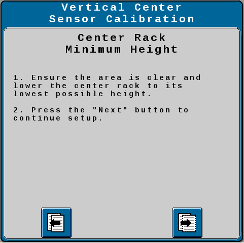
Lower the center rack to the lowest position. Select the Next button to continue the calibration.
Note: Most machines will skip this step.
-
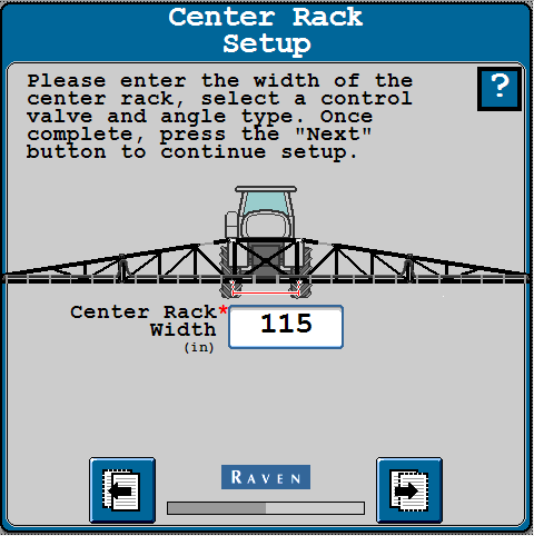
Enter the Center Rack Width. The center rack width is measured from the left boom pivot point to the right boom pivot point. The pivot point is where the boom rotates as it is raised/lowered. The pivot point is generally a horizontal steel pin.
-
Select Next.
-
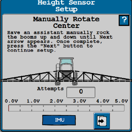
Machines that use an IMU
 Inertial Measurement Unit (Inertial Measurement Unit) for Center Rotation Measurement will complete the steps in the drop-down below. Machines that use a rotary position sensor will continue to the next step.
 Machines with an IMU
-
Verify the IMU orientation on the machine matches the image on the IMU Orientation page. If needed, select the rotate buttons on the right side of the tab to adjust the orientation.
-
If required, select the Redetect Orientation button to redetect the orientation of the IMU on the Downward Orientation page.
Note: The downward and forward orientations can be entered in the appropriate fields.
-
Select Next.
-
Verify the machine is parked on a level surface.
-
Select Calibrate Center Rack Angle.
-
After center rack angle calibration is complete, select Next.
-
-
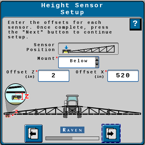
Enter the Z offset from the bottom of the spray tips to the bottom of the sensor lens for the identified sensor into the Offset Z field.
-
Enter the X offset from the boom pivot point (not the machine center line) to the sensor mounting location into the Offset X field.
-
Select Next.
-
Enter the Z and X offsets for the remaining sensors.
-
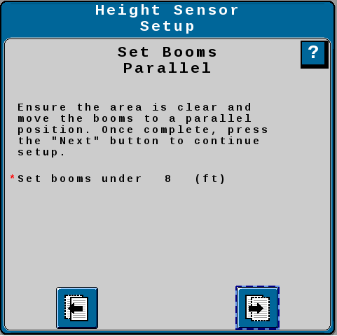
Set the booms parallel and under 8 ft. [2.4 m] from the ground.
-
Select Next.
-
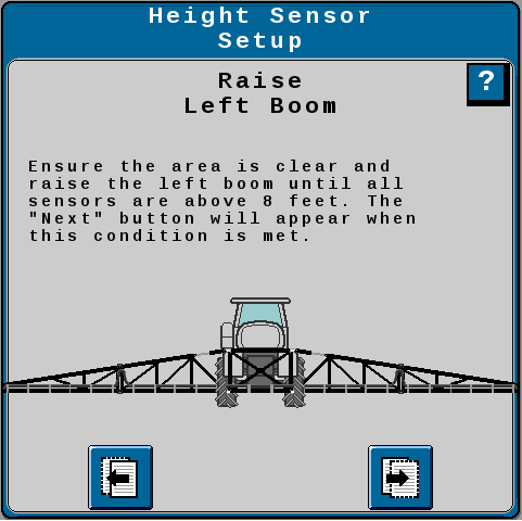
Raise the left boom until there is at least a 40 in. [101.6 cm] change in height.
-
Select Next.
-
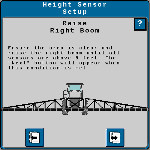
Raise the right boom until there is at least a 40 in. [101.6 cm] change in height.
-
Select Next.
-
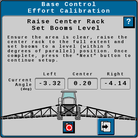
Machines that use a rotary position sensor for Center Rotation Measurement will complete the steps in the drop-down below. Machines that use an IMU will continue to the next step.
-
Raise the center rack and set the booms level.
Note: The boom will move on its own for the next few steps. Verify nobody is standing near the booms.
-
Select Next. The system will perform an automatic calibration sequence to determine the duty cycle required to keep the boom stationary.
-
If prompted, manually raise or lower booms and select Next to continue calibration.
-
Review the information on the Height Sensor Setup page.
-
Select Next.
-
Review the information on the System Summary page.
-
Select Next.
-
The AutoBoom® XRT Home screen will be displayed. Refer to AutoBoom® XRT Home Screen for more information on operating the Home Screen
Note: If features are not visible on the AutoBoom® XRT Home screen, it means those features are locked. To unlock these features, refer to Feature Unlocks.
Last Revised: Jul 2024
