Auto-Steer Calibration
The auto-steer calibration consists of the following component setup calibrations:
- Implement Steer Valve and Position Types
- Position Sensor Calibration
- Implement Control Calibration
- Master Roading Switch Calibration
- Position Sensor Calibration
- Auto-steering calibration
Note: Some of the settings listed above are only displayed while configuring a "generic" tuneset. A generic tuneset is a machine profile which uses the generic option in the Brand, Series, or Model fields on the Machine Selection page at the start of the initial calibration wizard. Review Guidance and GNSS Calibration for more information.
Implement Control Calibration
Note: Raise the implement so it is out of the ground during the calibration.
Note: Complete the following steps when calibrating a side shift implement steering system. When calibrating a disc system skip to Step 9.
-
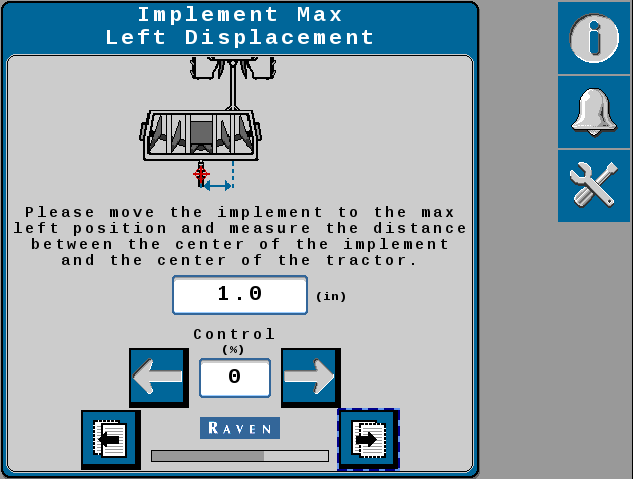
Use the on screen arrows to move the implement to the maximum left position.
Maximum Left Displacement Page
-
When the implement has reached the furthest left position, measure the displacement from the center position.
-
Enter the measured distance and select the Next button.
-
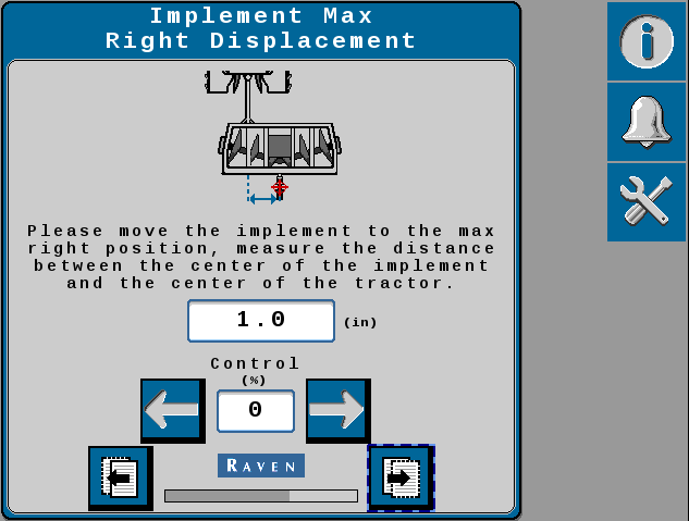
Use the on screen arrows to move the implement to the maximum right position.
Maximum Right Displacement Page
-
When the implement has reached the furthest right position, measure the displacement from the center position.
-
Enter the measured distance and select the Next button.
-
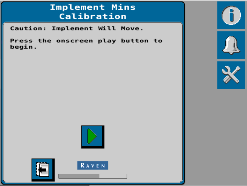
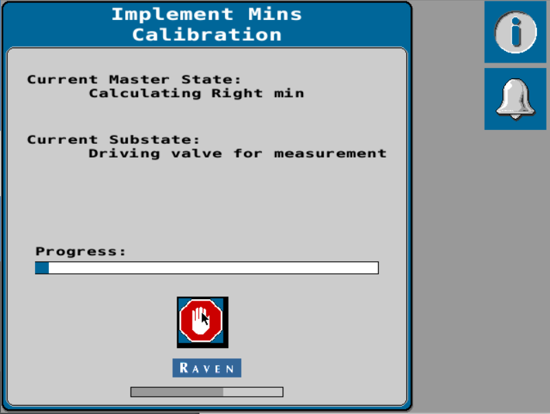
Set the Min % to the minimum value required to move the implement steering actuator.
-
The Max % can be used to limit the maximum speed of the implement steering actuator, if desired.
-
Use the Implement Control Setup screen to confirm implement steer actuator operation. Review the Implement Steer Control Settings for additional information on using this screen.
-
Select the Next button.
-
Review the Calibration Wizard Summary.
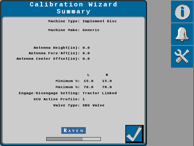
-
Select the Accept button to complete the calibration wizard and display the Home screen.
Last Revised: Nov 2024