Guidance and GNSS Calibration
Note: The following steps are intended to outline the calibration procedure. Some options shown will be dependent upon settings and options selected.
- Open the UT
 A Universal Terminal (formerly Virtual Terminal) is an electronic display or console capable of interfacing with ECUs on an ISOBUS network. menu of the display or field computer.
 - During the initial start-up of system, the operator will be presented with the Operator Liability prompt.
Note: Refer to the Operator Liability topic for more information.
- Select the guidance and steering terminal
 from the UT menu. The Machine Selection page is displayed.
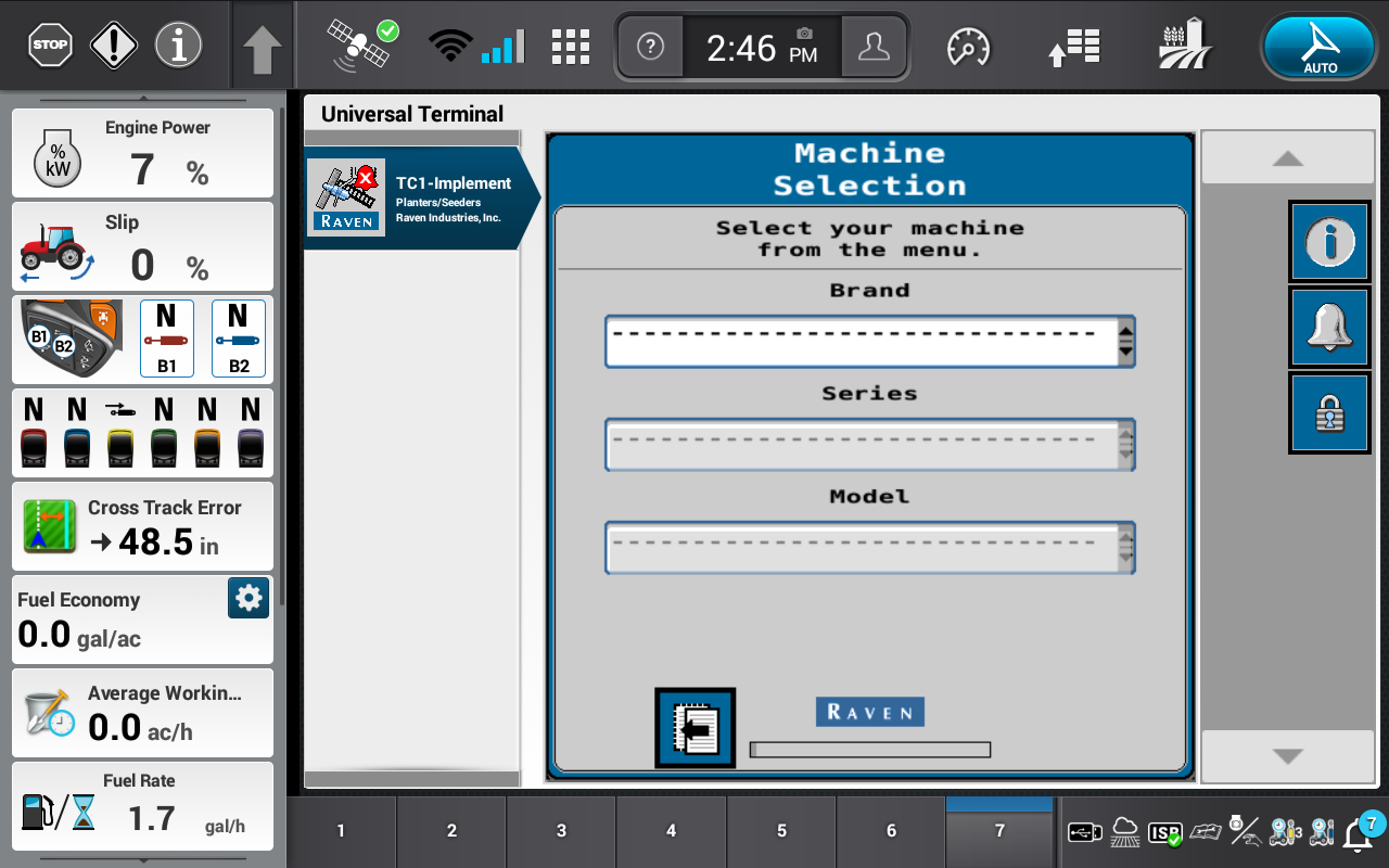
Note: The Slingshot® terminal icon only displays when calibrating the Raven RS1™.
- Confirm that the correct ECU Electronic Control Unit will be programmed by selecting the Information icon in the upper, right corner and matching the Hardware Serial Number to the ECU serial number mounted to the machine or implement.
Note: If the Machine Home page displays, the ECU is calibrated already for that terminal. Check other terminals for an ECU that has not been calibrated.
- The Machine Selection page will be displayed.
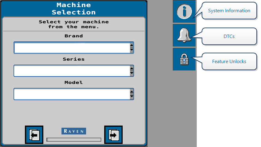
Note: System information, DTCs, and system test pages may be viewed during the initial calibration. For further information on these settings, review the following topics:
Note: The system health test pages provide additional diagnostic capabilities and allow the operator to test function of various machine controls and sensors.
- When configuring active implement guidance applications, use the Brand drop-down option to select ProTrakker™ or Spudnik.
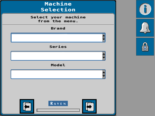
Note: If theses options do not fit the specific application, use the Brand drop-down option to select Generic. When using the generic brand setting, use the Series drop down to select the appropriate steering method (e.g. Implement Disc or Implement Side-Shift).
- Next, use the Series and Model options to select define the steering system and the implement in use.
- ProTrakker™
- Series - Select the series of ProTrakker™ installed.
- Model - Select the specific implement supported for use with the ProTrakker™ unit.
- Spudnik
- The series and model fields are automatically populated with supported Spudnik implement details.
Note: If using preconfigured (e.g. non-generic) tunesets, some machine/implement offset values will be pre-populated on the following pages of the initial calibration wizard. It is recommended to confirm these values on your specific machine and implement for best tuning and performance.
- ProTrakker™
- Select the Next button.
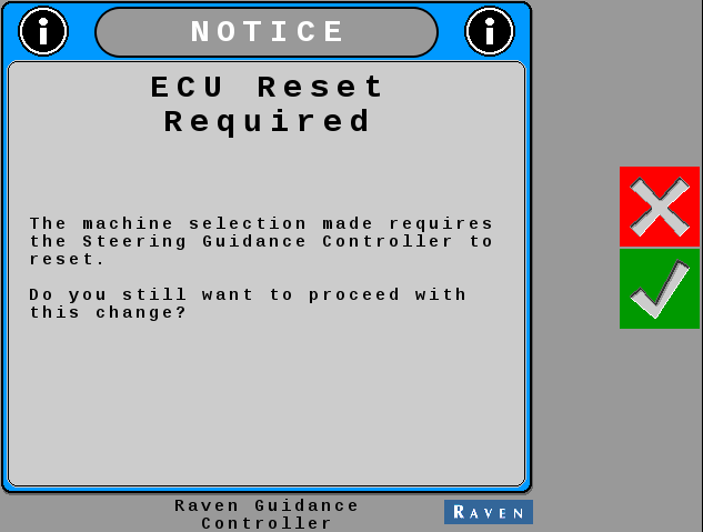
Note: The SC1™/TC1™ ECU is configured to steer tractors and sprayers from the factory. The ECU will need to be reset for implement steering operations and restarted before the initial calibration wizard can be completed. Complete the following steps to reset the ECU.
- On the ECU Reset prompt, select the Accept button.
- Wait for the ECU to restart and the terminal to repopulate in the UT menu.
- When the ECU restarts, select the Implement Guidance and Steering terminal from the UT menu.
- Select the Next button.
- Once the Machine options are set, select the Next page button to proceed with the initial calibration.
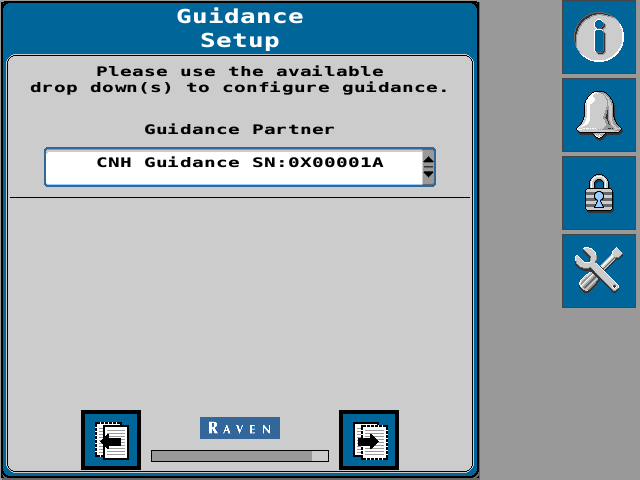
- Use the Guidance Partner drop-down to select the CNH Guidance as the guidance partner.
- The system will attempt to detect a steering partner.
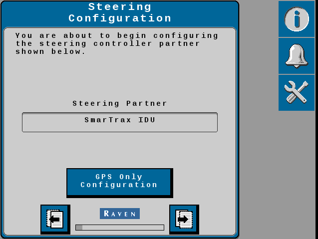
- If no steering partner is detected, or if steering will not be used in the current application, select the GPS Only Configuration button. In this configuration, auto-steer features will not be available.
Note: The GPS Only Configuration should not be used with implement guidance and steering systems.
- If a steering partner is detected, select the Next button to calibrate both the GNSS Global Navigation Satellite System and auto-steering features of the system.
- If no steering partner is detected, or if steering will not be used in the current application, select the GPS Only Configuration button. In this configuration, auto-steer features will not be available.
- Use the drop-down to select the appropriate GNSS receiver.
Note: When configuring a system with the RS1™, the receiver selection page may not display.
Differential Global Positioning System is an enhancement to standard GNSS/GPS messages to provide better position accuracy. correction source for both the implement and tractor GNSS receivers must be set to RTK Real-time Kinematic.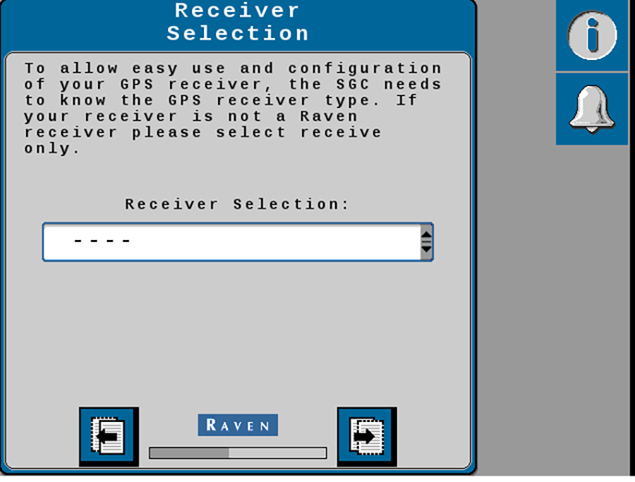
Note: Receiver setup will need to be done prior to performing the steering calibration. Only the Raven700S™, Vector Pro, and Cygnus GNSS receivers will be automatically configured via the SC1™. All other receivers will need to have the serial port manually configured to output the following messages at the following rates:
Table. GNSS Message Settings Message Frequency (Hz) Baud Message Port RTK Input GGA 10 115200 372 receivers use port A
392 receivers use port C
372 receivers use port B
392 receivers use port 3
VTG 1 GSV 0.1 ZDA 1.0 GSA 0.1 GST 1 GRS 1 Note: 372/392 GNSS receivers must be configured via AgRemote.
- Select the Next page button.
- Use the Tractor Type drop-down to select the steering type of the machine in use with the active implement guidance solution.
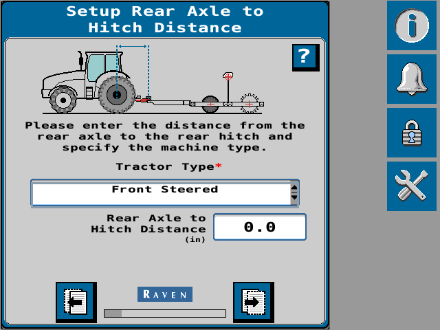
Note: This page is not shown while configuring a Generic tuneset. A new calibration must be done if the tractor pulling the implement changes.
- Use the distance input field to enter the measurement from the rear axle of the tractor to the hitch point.
Note: The axle to hitch distance is measured from the rear axle of the tractor to the pivot point of the tongue of the implement.
- Select the Next page button.
- Select the input field to enter the full actuator range. Enter the full linear range of a hitch actuator or the angular range of a wheel actuator.
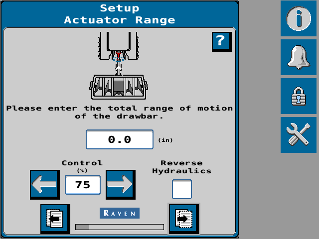
Note: This page is not shown while configuring a Generic tuneset. Enter the full actuator range. Do not measure the range to the center of the actuator.
- Touch and hold the left and right arrow buttons to manually move the actuator.
- Toggle the Reverse Hydraulics check box if the left and right arrows move the implement in the opposite direction than expected.
- Select the Next page button.
- Use the input field to enter the distance from the pivot point of the implement tongue to the working point.
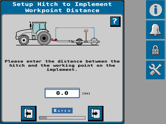
Note: This page is not shown while configuring a Generic tuneset. The working point of the implement is where the agronomic task of the implement is performed. If there are multiple working sections, measure to the point between the sections. Example Seeder with front and rear gangs.
- Select the Next page button.
- Use the input field to enter the distance from the pivot point of the implement tongue to the pivot point of the implement.
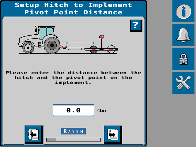
Note: This page is not shown while configuring a Generic tuneset. The pivot point of the implement is typically at the implement wheels or center of the tracks.
- Select the Next page button.
- Enter the Antenna Fore/Aft measurement in the units displayed on the page.
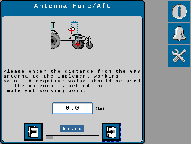
Note: The Antenna Fore/Aft Offset is measured from the working point of the implement to the center of the implement GNSS antenna. A negative value should be entered if the GNSS antenna is located behind the working point.
- Select the Next page button.
- Enter the Antenna Center offset measurement in the units displayed on the page.
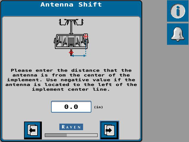
Note: The Antenna Center Offset is measured from the center line of the implement to the center of the GNSS antenna. A negative value should be entered if the GNSS antenna is located to the left of the center line.
notice

For best performance of the active implement guidance system, it is important to mount the GNSS receiver on or close to the center-line of the implement.
- Select the Next page button.
- Enter the Antenna Height measurement in the units displayed on the page.
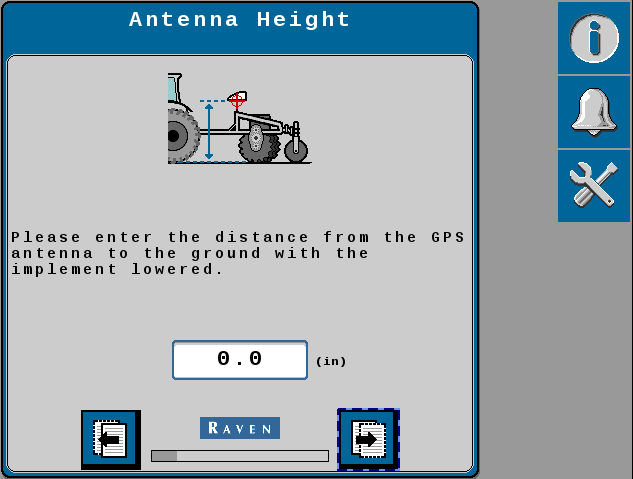
Note: The Antenna Height is measured from the ground to the center of the GNSS antenna with the implement lowered to working position.
- Select the Next page button to proceed.
- Select the appropriate GNSS Differential Source from the drop-down options list.
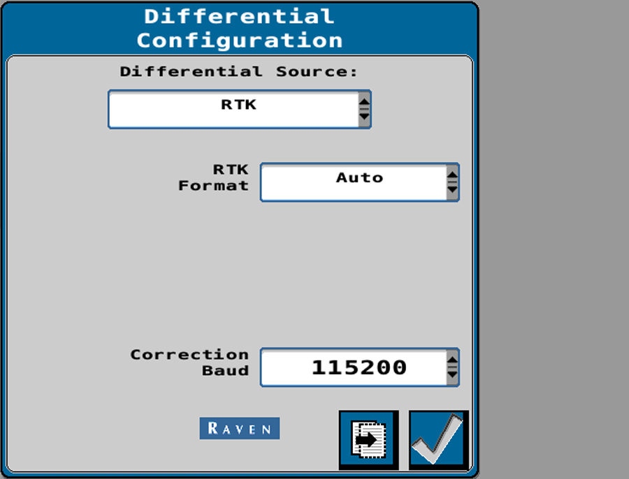
Note: Some differential sources may require a feature unlock or subscription. Refer to Feature Unlocks Tab for additional assistance with entering feature unlocks. Contact a local Raven dealer for assistance with purchasing feature unlocks or subscriptions.
The GNSS receivers on both the tractor and implement must be using the same differential source. Make sure to select the same settings for both GNSS receivers. Review GNSS Receiver Initial Setup for information on recommended settings.
The default settings for RTK Format (Auto) and Correction Baud (115200) are recommended.
- Select the Next page button.
- Review the GPS Status Information page.
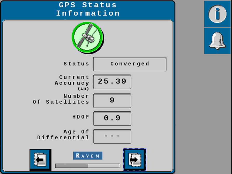
Note: The system must detect a converged GNSS status and display a green shield to successfully complete the terrain compensation calibration procedure.
-
Last Revised: Nov 2024