Auto-Steer Calibration
The auto-steer calibration consists of the following component setup calibrations:
- Implement Steer Valve and Position Types
- Position Sensor Calibration
- Furrow Calibration
Implement Steer Valve and Position Types
The following steps are only available in the calibration wizard when configuring a "Generic" machine type.
Valve Type
-
Use the drop-down list to select the type of valve used to steer the implement.
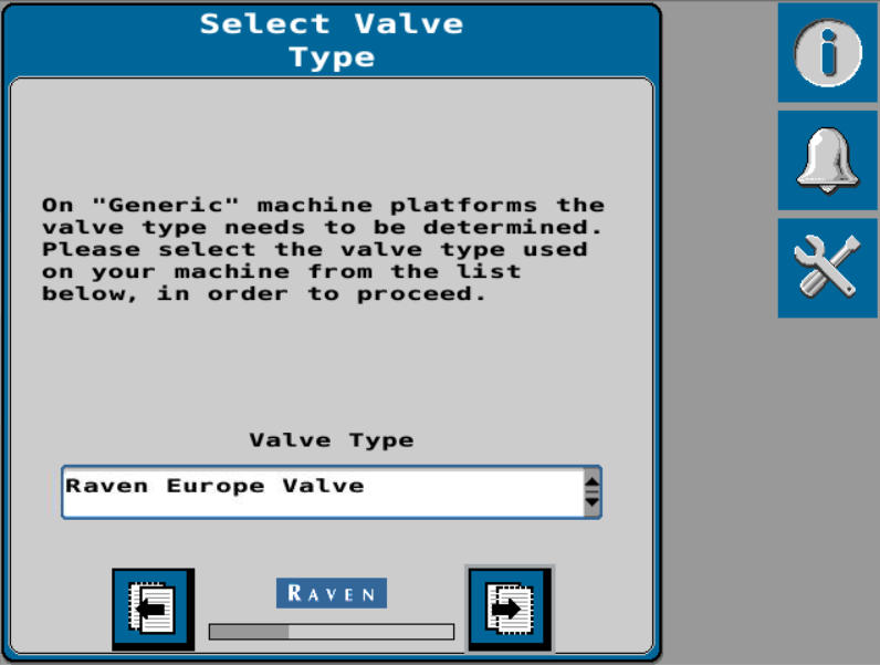
Note: The Select Valve Type page only displays when setting up a generic tuneset.
-
Select the Next button.
Position Sensor Type
-
Use the drop-down list to select the type of sensor used to detect the implement position.

Note: The Select Position Sensor Type page only displays when setting up a generic tuneset.
-
Select the Next button.
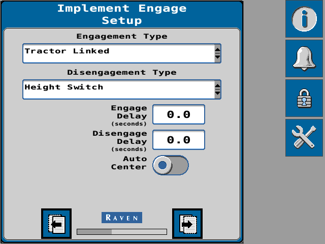
Engagement Type
-
Use the Engagement Type drop-down option to select how the operator will engage the implement steering system during in-field operations.
- Tractor Linked - Implement guidance engages when tractor auto-steering engages.
- Height Switch - Implement engages when implement is lowered.
- Field Computer Only - Implement engages via the UT
 A Universal Terminal (formerly Virtual Terminal) is an electronic display or console capable of interfacing with ECUs on an ISOBUS network. independent from machine engage status.
 - ISO Hitch Position/Status - Implement engages via a certain hitch position which is broadcast over the ISObus.
Note: When an ISO hitch position/status message is available, the engage/disengage type can be set to ISO Hitch Position/Status. Refer to the Implement Disengage/Engage Settings (Implement Steering Only) for additional information on implement engage setup options.
-
Use the drop-down list to select how the operator will disengage the implement steering system during operation.
- Tractor Linked - Implement guidance disengages when tractor auto-steering disengages.
- Height Switch - Implement disengages when implement is raised.
- Field Computer Only - Implement disengages via the UT independent from machine disengage status.
- ISO Hitch Position/Status - Implement disengages via a certain hitch position which is broadcast over the ISObus.
Note: When an ISO hitch position/status message is available, the engage/disengage type can be set to ISO Hitch Position/Status.
-
Headland Follow Mode allows the implement to follow the tractor driven path through a headland turn. Use the Headland Follow Mode Trigger drop down option to select how the system will transition into or out of follow mode. Select:
- Height Switch - Implement engages when implement is lowered.
- Field Computer Only - Implement engages via the UT independent from machine engage status.
Note: Refer to the Implement Disengage/Engage Settings (Implement Steering Only) for additional information on implement engage setup options.
-
Set the desired Engage Delay in seconds. If a non-zero value is entered, the implement guidance will not engage until the signal is received and the time, in seconds, as entered into the field elapses.
-
Set the desired Disengage Delay in seconds. If a non-zero value is entered, implement guidance will remain engaged after the signal to disengage guidance is received and the time, in seconds, as entered into the field elapses.
-
Toggle the Auto Center option on to automatically center the implement after implement guidance is disengaged.
-
Select the Next button.
Furrow Calibration
Note: Complete the following steps when calibrating a plough implement steering system.
-
Raise the implement and select the Narrow button to adjust the implement to narrowest furrow width.
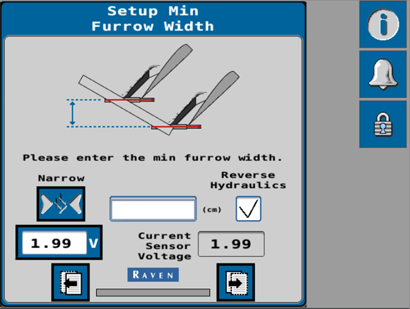
Note: Use the Reverse Hydraulics check-box option as needed to switch the direction which the implement moves when using the narrow button.
-
Measure the width between plough bodies.
 warning
Hydraulic systems may lose pressure and lower or drop an implement unexpectedly. Avoid working under a raised implement. Lower the implement to the ground or use a mechanical lock to secure hydraulics before working around the implement. Note: Do not enter the overall width of the plough. The width between bodies must be measured perpendicular to the direction of forward travel.
For best results, measure the width of multiple plough bodies and enter the average measurement.
-
Enter the measurement in the units shown on the page.
-
Select the voltage button to update the voltage for the minimum furrow width. The current sensor voltage should now display in the voltage button display.
-
Select the Next button.
-
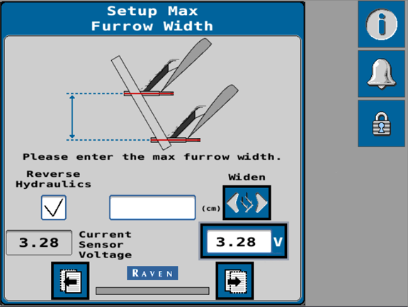
Raise the implement and use the Widen button to adjust the implement to widest furrow width.
-
Measure the width between plough bodies.
warning
Hydraulic systems may lose pressure and lower or drop an implement unexpectedly. Avoid working under a raised implement. Lower the implement to the ground or use a mechanical lock to secure hydraulics before working around the implement. Note: Do not enter the overall width of the plough. The width between bodies must be measured perpendicular to the direction of forward travel.
For best results, measure the width of multiple plough bodies and enter the average measurement.
-
Enter the measurement in the units shown on the page.
-
Select the voltage button to update the voltage for the maximum furrow width. The current sensor voltage should now display in the voltage button display.
-
Select the Next button.
-
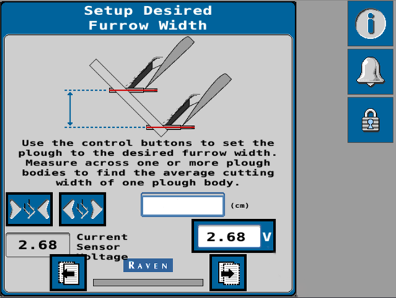
Raise the plough and use the control buttons to set the implement to the desired working width.
Note: The ideal furrow working width is 1.5 times the working depth.
-
Measure the physical furrow width between plough bodies as shown in the figure on the screen.
warning
Hydraulic systems may lose pressure and lower or drop an implement unexpectedly. Avoid working under a raised implement. Lower the implement to the ground or use a mechanical lock to secure hydraulics before working around the implement. Note: Do not enter the overall width of the plough. For best results, measure more than one furrow width and enter the average measurement.
-
Enter the measurement in the units shown on the page.
-
Select the voltage button to update the voltage for the working furrow width. The current sensor voltage should now display in the voltage button display.
-
Select the Next button.
-
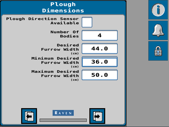
Enable the Plough Direction Sensor option to allow the system to detect and use the plough direction for future references.
-
Enter the number of plough bodies in the Number of Bodies field.
Note: The system will use the entered furrow widths and this value to calculate the overall guidance width of the plough.
-
Use the Desired Furrow Width field to set the desired position for the plough bodies during operation. This sets the position which the system will attempt to maintain while operating the plough steering system during guidance operation.
-
Use the Minimum Desired Furrow Width to set the lowest or narrowest physical furrow position which the system will allow during operation.
-
Use the Maximum Desired Furrow Width to set the highest or widest physical furrow position which the system will allow during operation.
-
Confirm the settings shown on this page and select the Next button.
-
Raise the implement.
-
Select the Start button to begin the automatic calibration of the hydraulic valve.
warning
The machine will steer automatically. Be sure the area around the vehicle is clear of people and obstacles before engaging the auto-steer system.
To disengage auto-steering at any time, toggle the roading switch, select the on-screen Stop button, or (as applicable) turn the steering wheel.
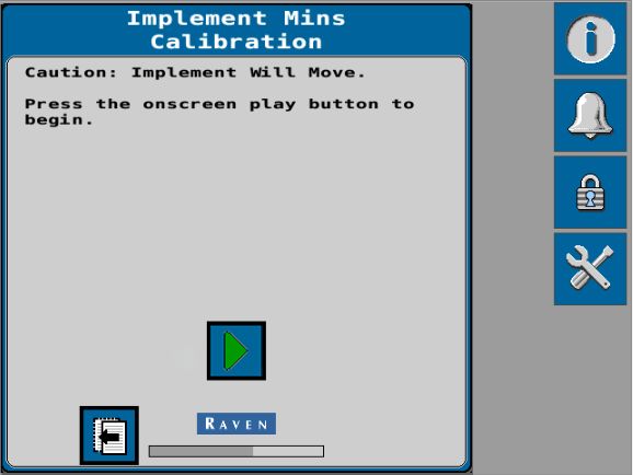
Note: During the calibration, the plough bodies will move fully through the range of calibrated settings. It is important that the plough not be in contact with the ground during the calibration process.
-
Once the calibration is complete, select the Next button.
-
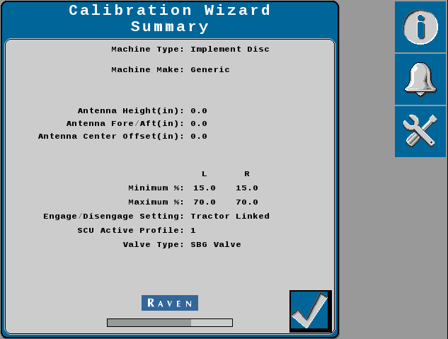
Review the Calibration Wizard Summary.
-
Select the Accept button to complete the calibration wizard and display the Home screen.
Last Revised: Sep 2024