Mount In-Cab Components
The following steps offer cab installation and connection instructions specific to the OMNiDRIVE™ system.
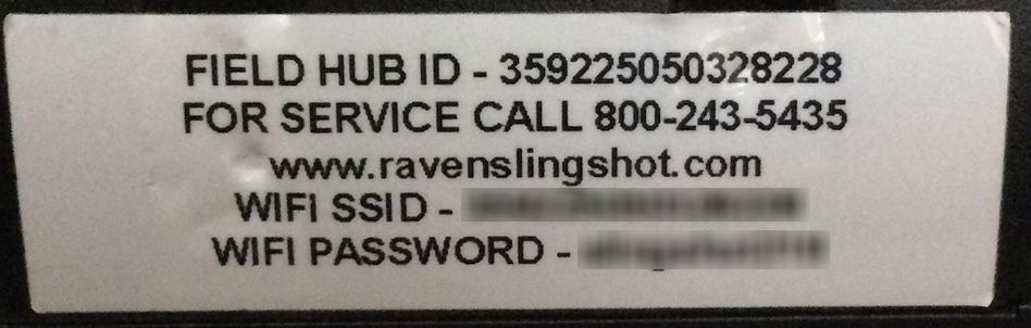
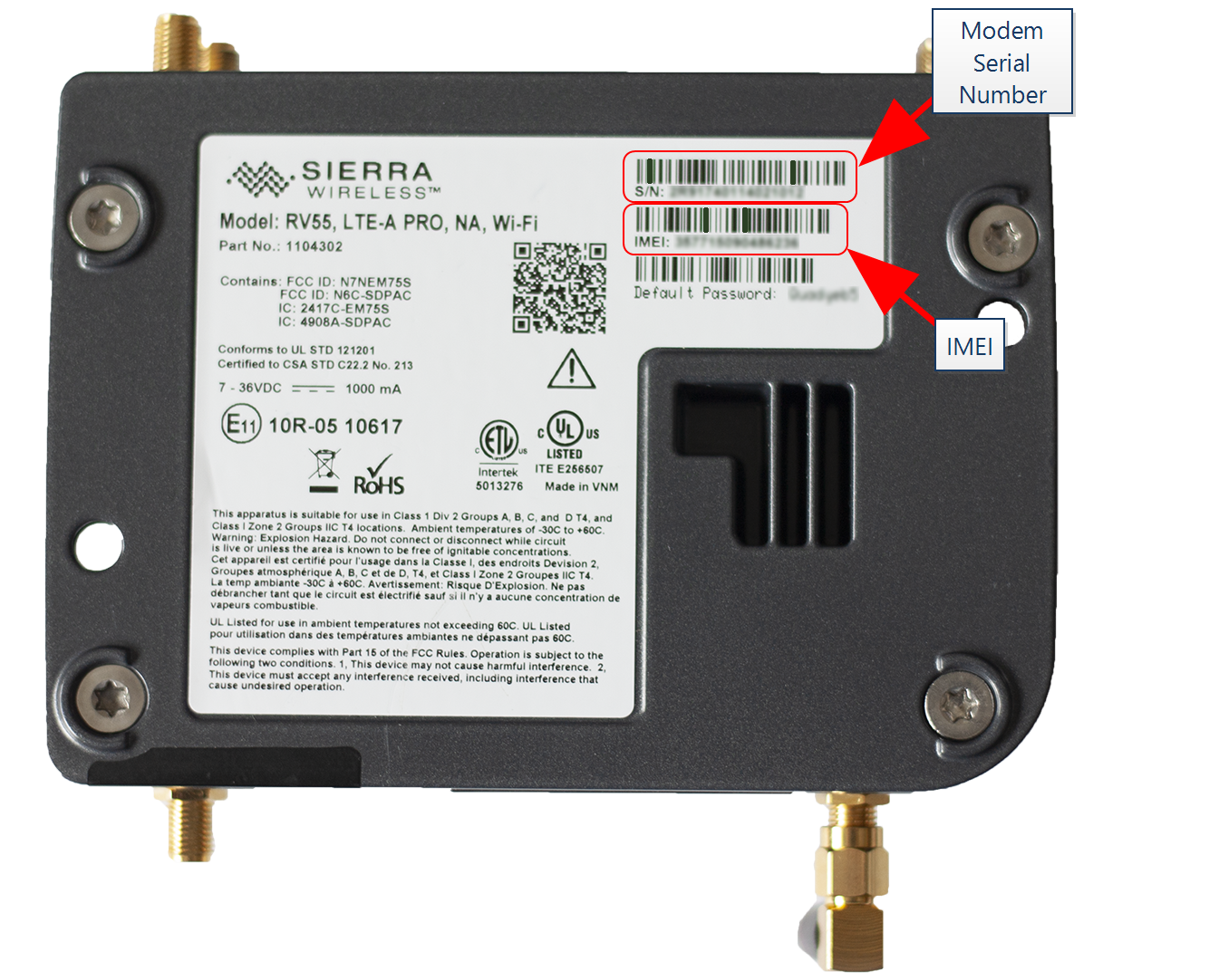
Note: During the installation process, note the serial number and bar code of the following devices and the machine on which each device is installed:
- Slingshot®Field Hub
- RS Lite
- CR7™
This information will be required during device registration and field provisioning procedures and will help locate each device within the Slingshot® portal.
Note: Please allow up to 4 business days to activate the Field Hub. Once activation has been completed, a confirmation email will be sent to the customer and an OTA![]() (Over the Air) Software updates and other information pushed from Slingshot® servers via the Slingshot® system. software update will be pushed to the Field Hub the next time the device powers up. It may be recommended to complete and submit the OLAF
(Over the Air) Software updates and other information pushed from Slingshot® servers via the Slingshot® system. software update will be pushed to the Field Hub the next time the device powers up. It may be recommended to complete and submit the OLAF![]() Online Activation Form procedures for the Field Hub on all OMNiDRIVE™ machines. Refer to the following for additional assistance:
Online Activation Form procedures for the Field Hub on all OMNiDRIVE™ machines. Refer to the following for additional assistance:
OMNiDRIVE™ System Diagram - Combine
Mount the Tablet
Note: There are multiple ways to mount the tablet in the cab. Included are an example of mounting to an OEM display and to a bracket.
Mount the Tablet to an OEM Display
- Place the tablet face-down on a flat surface.
- Secure the large, square RAM® base to the back of the tablet using the provided inserts and M4 screws (P/N 311-0005-030).
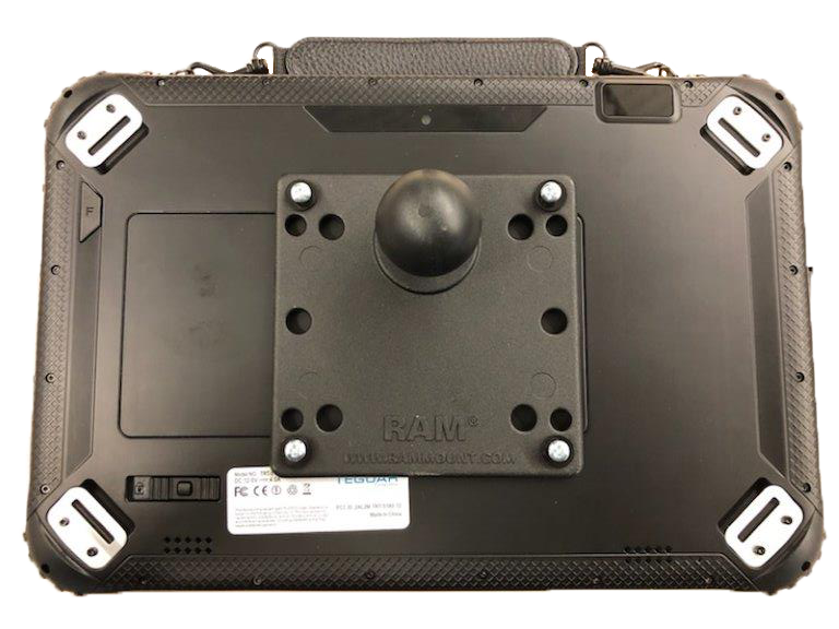
Note: The RAM® base may be oriented on the tablet to accommodate different mounting configurations as desired.
- Secure the round RAM® base to the display mount (P/N 103-0159-024) as shown below.
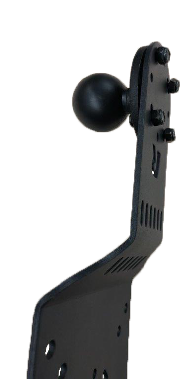
- Remove the OEM display and install the RAM® display mount between the OEM display and bracket.
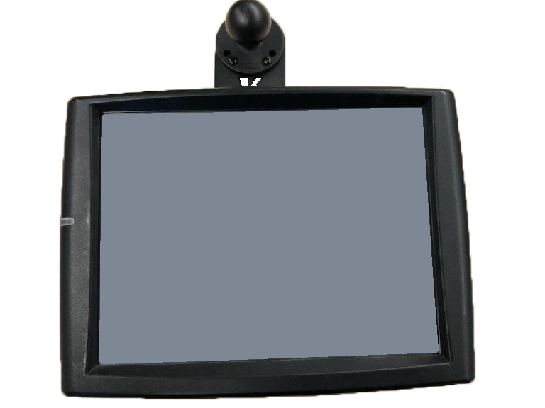

- Secure the RAM® socket arm to the base plates to mount the tablet above the OEM display.
Note: The display bracket and socket arm may be rotated to mount the tablet next to the OEM display.
Mount the Tablet to a Bracket
- Place the tablet face-down on a flat surface.
- Secure the large, square RAM® base to the back of the tablet using the provided inserts and M4 screws (P/N 311-0005-030).
Note: The RAM® base may be oriented on the tablet to accommodate different mounting configurations as desired.
-
Install the ball mount to the bracket.
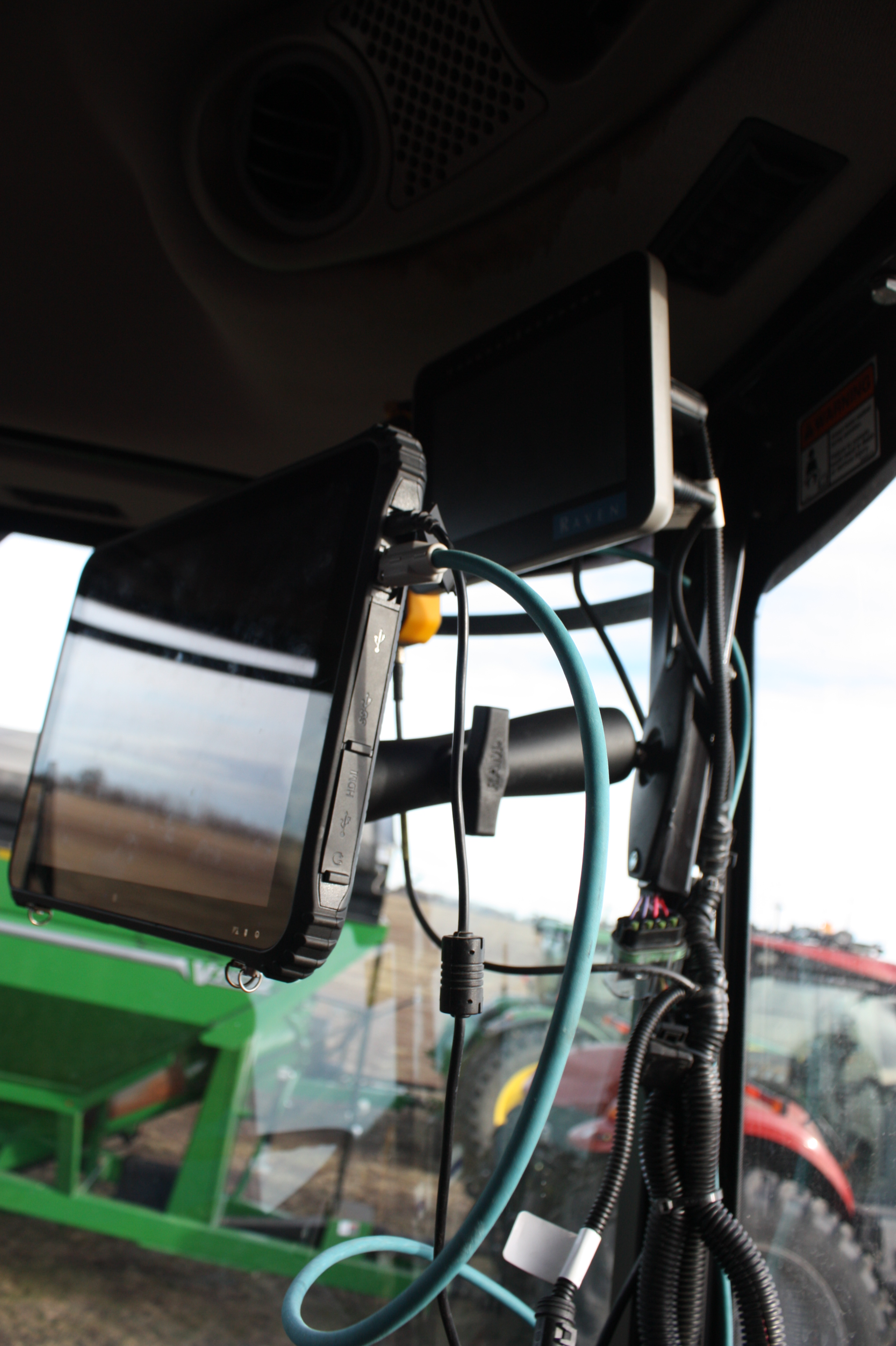
-
Mount the tablet to the ball mount using the socket arm.
Mount the Slingshot® Field Hub and Ethernet Switch
Note:
|
notice |
|
|---|---|
|
|
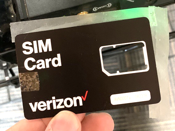
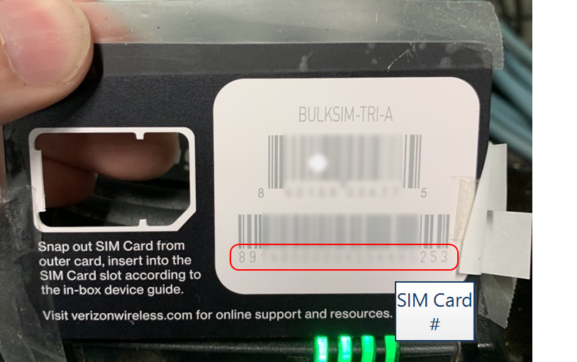
The information affixed to the bottom of the Field Hub will be required to activate the device and provision the OMNiDRIVE™ system. Before mounting the Field Hub, it is strongly recommended to remove the SIM |

- Use the supplied hardware to mount the Slingshot® Field Hub (P/N 063-0173-992) and Ethernet switch (P/N 063-2610-012) to the Slingshot®/Ethernet switch bracket (P/N 107-2610-024).

- Place the Field Hub/Ethernet switch assembly on the floor of the combine. Select a location where the bracket and cables will be out of the way, but still visible.
Note: Review the Field Hub Installation Manual for additional instructions on mounting and connecting the Field Hub antennas.
Mount the CR7™ and E-Stop
- Secure the CR7™ field computer to the mounting bracket (P/N 107-2610-025) using the supplied hardware.
- Use the provided 2-sided tape to secure the hand-held E-Stop
 Emergency stop button or switch. to the mounting bracket.
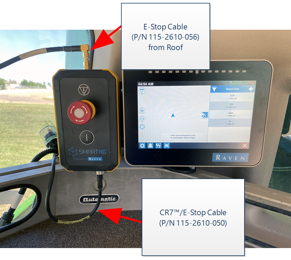
- Use the provided RAM® Mount and hardware to mount the bracket assembly within easy reach of the operator seat.
- Proceed to the Mount the Combine Roof Array topic to proceed with the installation process.
Last Revised: Jul 2024