Mount the Combine Roof Array
|
|
|
|---|---|
|
|
Use caution while working on the cab roof or standing on exterior surfaces. Surfaces may be uneven or slippery and hardware or harnesses may present tripping hazards. Contact a local equipment dealer for additional information or assistance with working on the roof or from an elevated position on a specific make and model machine. |
 warning
-
Metric socket set - 5 to 24 mm
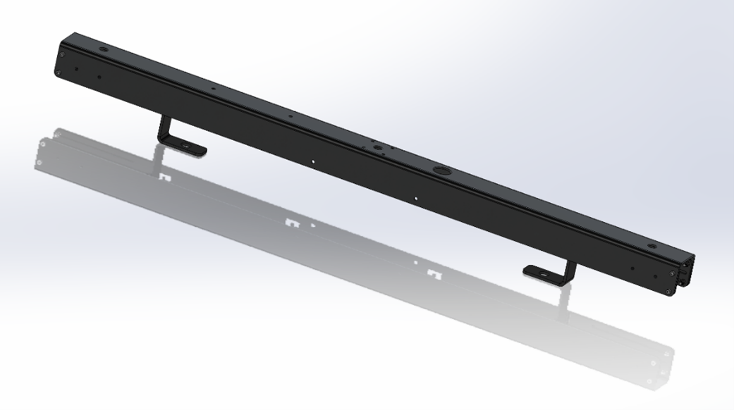
Complete the following steps to assemble and mount the antenna bracket, including the radio, and RS Lite.
OMNiDRIVE™ System Diagram - Combine

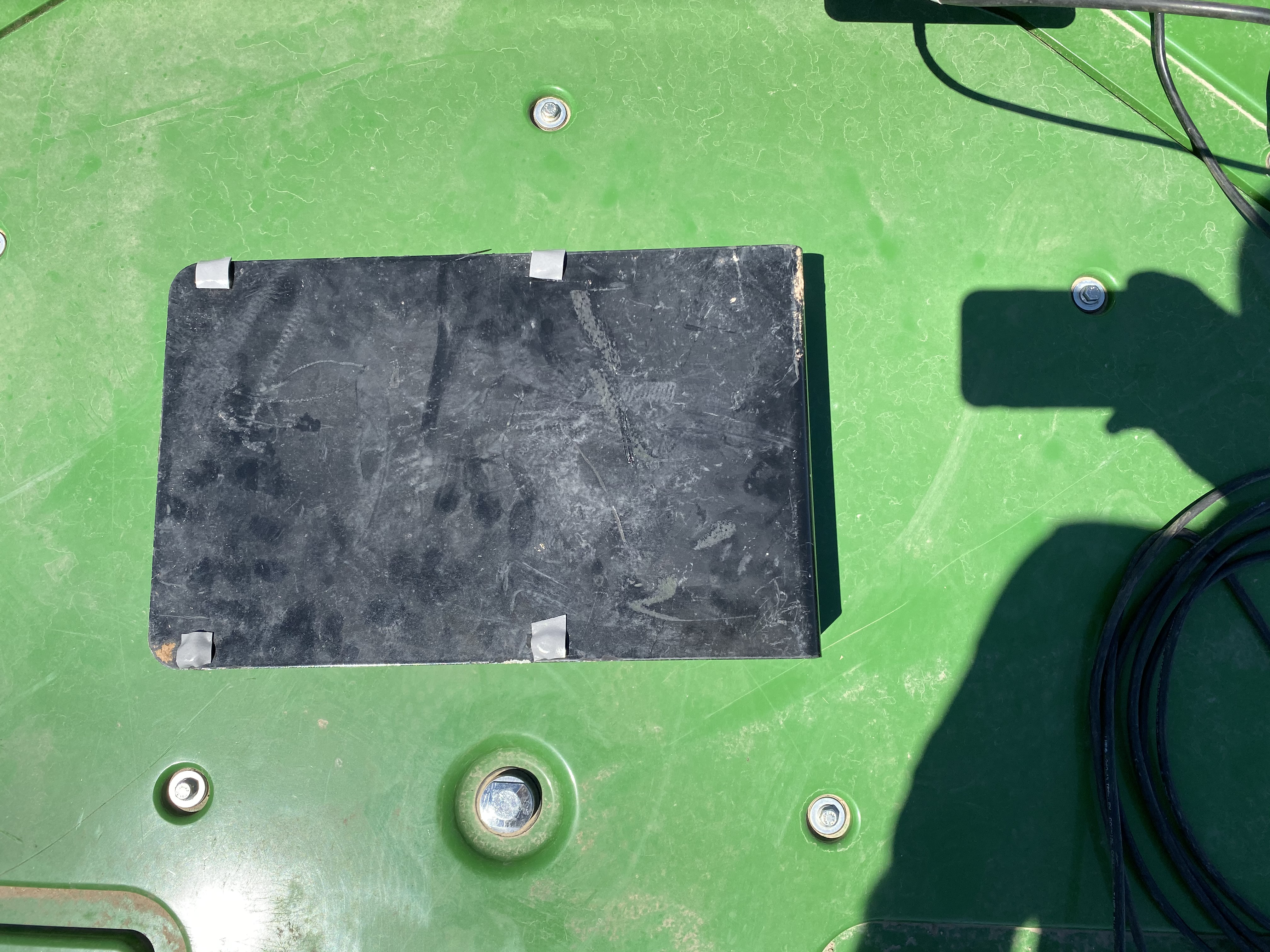
- Use the supplied bolts (P/N 311-4050-139N) and nuts (P/N 312-4000-216) to mount the RS Lite (P/N 063-0174-121) to the RS Lite mounting bracket (P/N 107-2610-023).

Note: Pass the bolts up through the bottom, flat face of the mounting plate so that the bolt heads are facing down toward the cab roof.
- Apply the supplied tape (P/N 332-0000-044) to the bolt heads to help prevent the bolts from contacting the cab roof.
- Use the supplied bolts (P/N 311-4050-136N) and nuts (P/N 312-4000-216) to fasten the mounting bracket to the antenna bracket assembly (P/N 063-2610-015) as shown in the figure above.
Note: It may be necessary to adjust the height of the RS Lite mounting bracket while securing the antenna bracket assembly to the roof.
- Secure the radio (P/N 063-2610-003) to the radio mounting bracket (P/N 107-2610-022) using the supplied bolts (P/N 311-4050-095N) and nuts (P/N 312-4000-215).
- Mount the radio bracket assembly to the top of the antenna bracket assembly with the bolts (P/N 311-4050-139N) and nuts (P/N 312-4000-216).
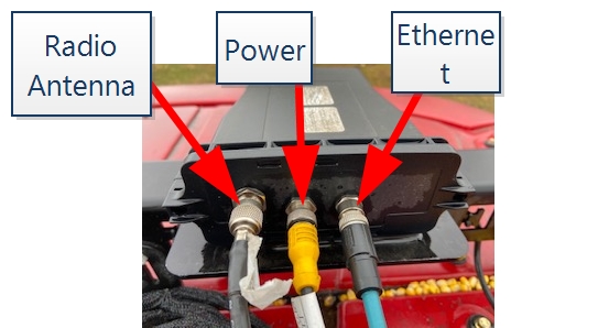
- Connect the radio cable (P/N 115-2610-023) to the radio.
- Connect the E-Stop
 Emergency stop button or switch. cable (P/N 115-2610-056) to the E-Stop antenna.
 - For Case IH combines remove the legs of the antenna bracket and flip them around to accommodate the narrower bolt spacing.
- On top of the cab roof, remove two roof bolts toward the front of the cab.
- Place the antenna bracket assembly on the roof and line up the holes.
Note: If necessary, loosen the small bolts on each side of the antenna bracket and adjust the bracket to fit the mounting posts.
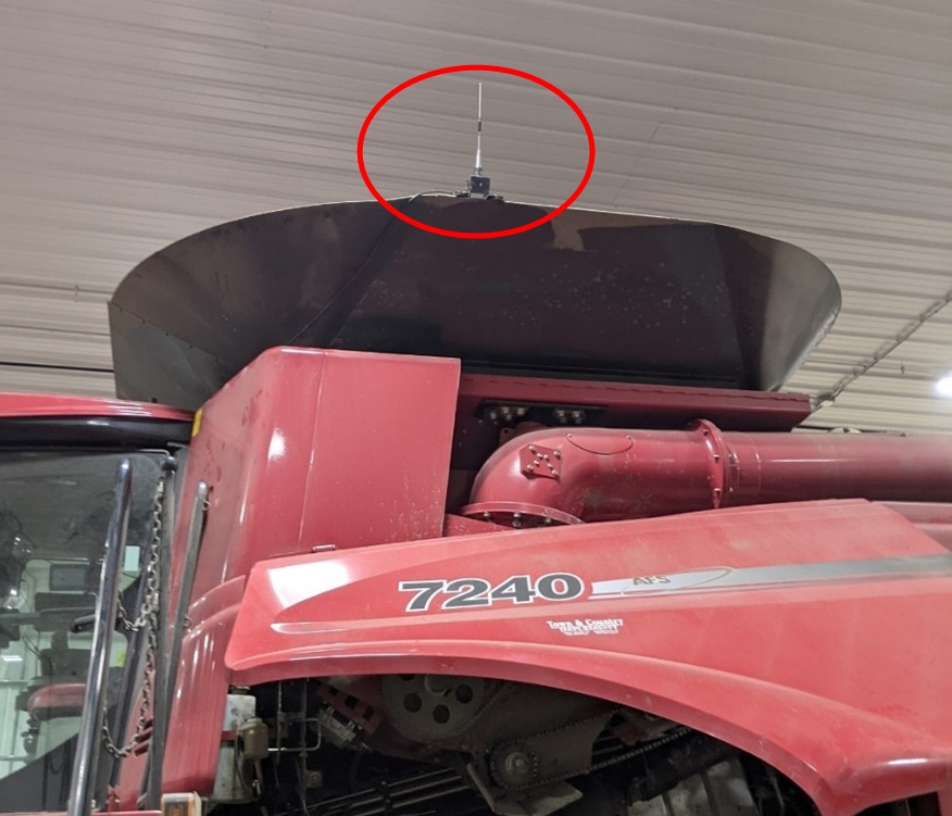
- Find a suitable location to mount the radio antenna bracket (P/N 107-2610-063) in an unobstructed area of the machine. Avoid mounting the antenna right next to other antennas or surfaces that will obstruct radio communication with the tractor as it approaches the combine for grain unloading. Be sure to mount the bracket where it and the associated radio cable will not be damaged by the actuation of the grain tank extensions, grain auger, or any other moving parts.
-
Example of a possible radio antenna location.
-
If a suitable magnetic location is not available, the radio antenna bracket can be attached to the two plate assemblies (P/N 063-0172-971). The plate assemblies can be attached to the machine with the pre-installed double sided adhesive on the plates.
- Install the radio antenna (P/N 121-0000-053) and radio antenna mount (P/N 121-0000-054) onto the radio antenna bracket (P/N 107-2610-063) in the proper orientation for the selected mounting configuration.
- Install the two magnet plates (P/N 418-0000-013) to the radio antenna bracket with two M6x20 mm hex bolts (P/N 311-4050-136N), two M6 lock nuts (P/N 312-4000-216), and two M6 washers (P/N 313-6000-010N).
- Install the radio antenna bracket assembly.
- Connect the radio antenna cable (P/N 115-2610-023) to the radio antenna.
- Proceed to the Connect Combine OMNiDRIVE™ System Cables for assistance with the final connections to the roof array and antenna components of the OMNiDRIVE™ system on the combine.
|
|
|
|---|---|
|
|
Route cables to avoid creating a tripping hazard and away from possible damage due to pinch points, heat generating and moving components, etc. |

Note: If a stronger mounting setup is desired, the bracket can be directly mounted to a surface without using the magnet plates by drilling mounting holes.
Last Revised: Jul 2024