Assemble the Antenna and Camera Brackets
-
Metric socket set - 5 to 24 mm
-
Metric wrenches
Assemble the Main Roof Bracket Frame
Note: When assembling the bracket frame, do not tighten hardware until the all struts and rails are assembled. Once all components are assembled loosely, go back and tighten all hardware to complete the bracket assembly.
- Locate the front (shorter) and rear (longer) struts of the bracket frame.
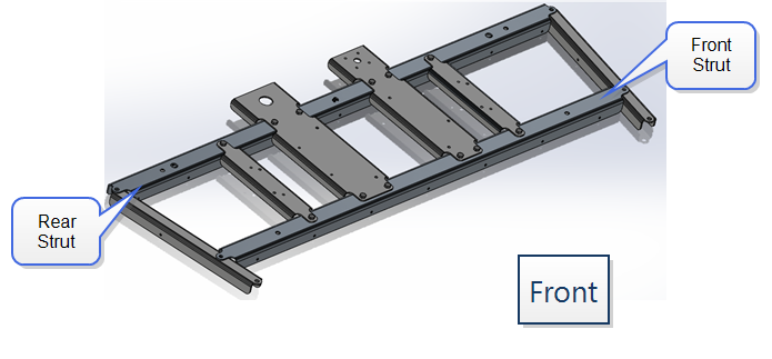
Note: The relief cuts in the front and rear struts must be facing forward on the final roof bracket assembly.
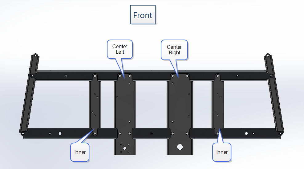
- Place the center left and center right rails on top of the front (shorter) and rear (longer) struts as shown in the figure above and secure with the provided M8 hardware.
Note: Both of the center rails must extend past the rear strut and are mounted to the top of the struts. Note that the center left rail is more narrow and provides a 5-hole pattern while the center right strut is wider and offers a large, circular hole toward the rear.
- Place the inner rails on top of the front and rear struts and secure with the provided M8 hardware.
Note: The inner rails are interchangeable and reversible.
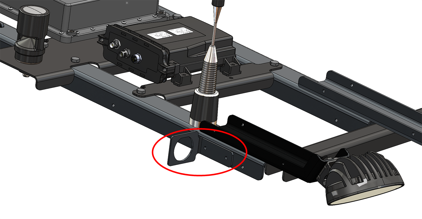
- Install the bulkhead bracket (P/N 107-2610-060) to the right side of the rear strut using the provided M5x12 hardware.
- Position the outer rails under the tabs on either end of the front and rear struts as shown in the figure above.
- Position the two side camera brackets (P/N 116-2610-006) on top of the front strut with the front corners of the bracket frame. Using the provided M8 hardware, secure the camera bracket, front strut, and outer rails.
Note: The flat face of the camera bracket should be facing down or flush with the front strut.
- Position the two side light brackets (P/N 116-2610-050) on top of the rear strut with the at the rear corners of the bracket frame. Using the provided M8 hardware, secure the light bracket, rear strut, and outer rails.
Note: The outer bolt on the light bracket (rear strut and outer rail) cannot be tightened until the antenna bracket is on the roof for mounting to the standoff. To assist with moving and lifting the antenna bracket onto the roof, it may be helpful to use the nuts removed from the standoff locations to temporarily hold the bracket at these locations.
- Secure the camera and light brackets to the assembly using the provided M8 hardware.
Mount Devices to the Roof Bracket
Note: During the installation process, note the serial number and bar code of the following devices and the machine on which each device is installed:
- Slingshot®Field Hub
- RS Lite
This information will be required during device registration and field provisioning procedures and will help locate each device within the Slingshot® portal.
Note: Please allow up to 4 business days to activate the Field Hub. Once activation has been completed, a confirmation email will be sent to the customer and an OTA![]() (Over the Air) Software updates and other information pushed from Slingshot® servers via the Slingshot® system. software update will be pushed to the Field Hub the next time the device powers up. It may be recommended to complete and submit the OLAF
(Over the Air) Software updates and other information pushed from Slingshot® servers via the Slingshot® system. software update will be pushed to the Field Hub the next time the device powers up. It may be recommended to complete and submit the OLAF![]() Online Activation Form procedures for the Field Hub on all OMNiDRIVE™ machines. Refer to the following for additional assistance:
Online Activation Form procedures for the Field Hub on all OMNiDRIVE™ machines. Refer to the following for additional assistance:
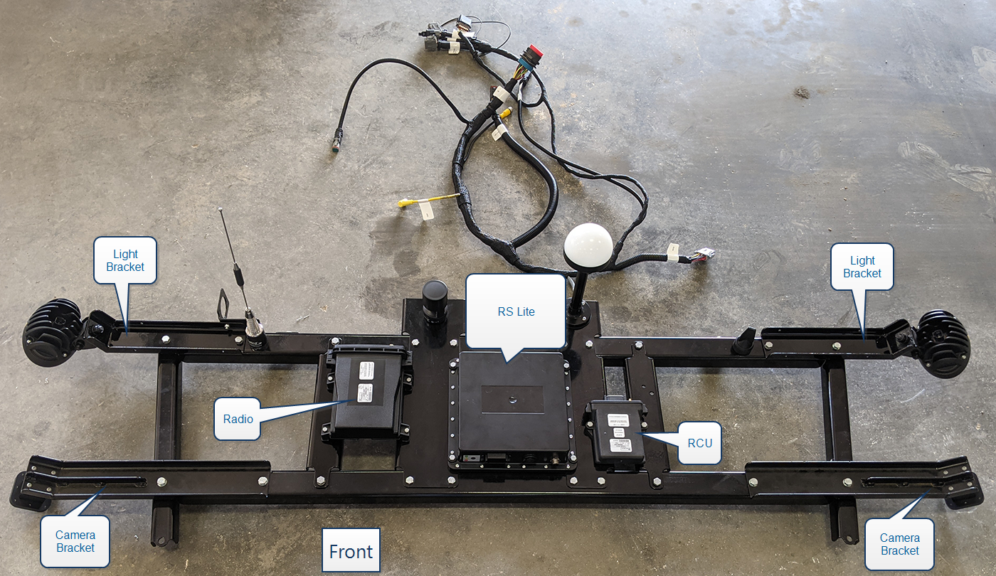
- Mount the RS Lite to the device plate using the supplied M6x30 hardware. The connectors on the RS Lite device must be facing toward the front of the roof bracket.
- Align the radio (P/N 063-2610-003) with the pre-drilled holes on the right side of the RS Lite and secure with the provided M5x30 hardware.
Note: The connectors on the radio must be pointing toward the back of the roof bracket.
- Align the RCU (P/N 063-2610-019) with the pre-drilled holes on the left side of the RS Lite and secure with the provided M6x30 hardware.
Note: The connectors on the RCU must be pointing toward the back of the roof bracket.
- Mount the radio antenna (P/N 121-0000-053) to the rear strut in the far right hole.
- Mount the E-Stop
 Emergency stop button or switch. antenna (P/N 121-0000-052) to the rear strut in the far left hole.
 - Mount the audible alarm (P/N 063-2610-025) to the center, right rail behind the rear strut.
- Feed the beacon connector (labeled J24 BEACON) on the RS Lite MCM cable (P/N 115-2610-094) through the left, center antenna bracket rail, the beacon flange, and beacon standoff.
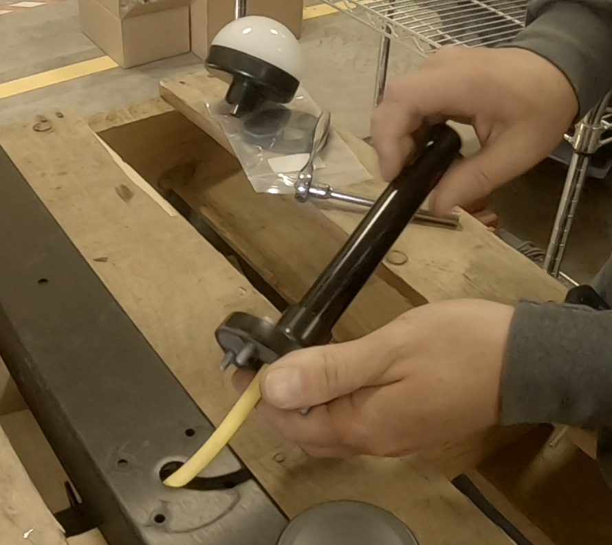
- Insert the beacon cable connector into the port on the bottom of the beacon.
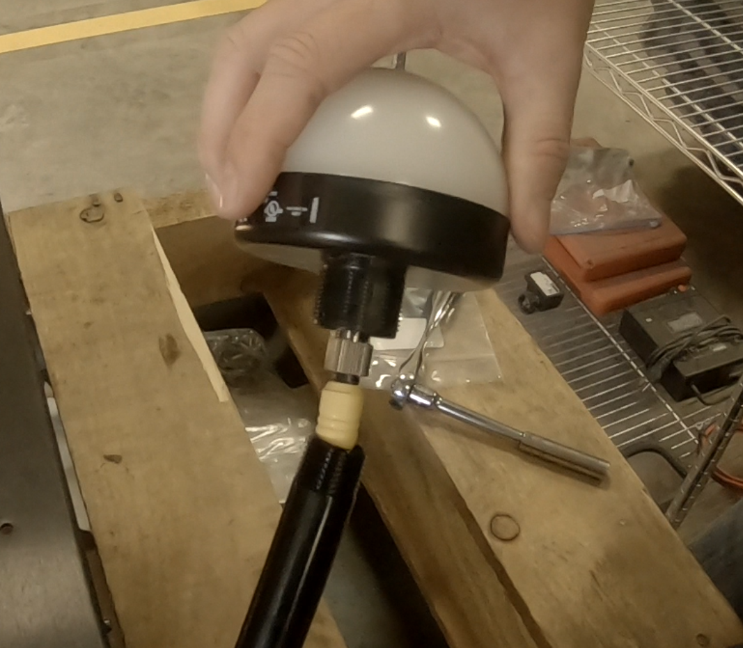
- Thread the beacon and flange onto the standoff.
Note: To avoid twisting the beacon cable, hold the beacon light stationary while threading the flange and standoff onto the beacon.

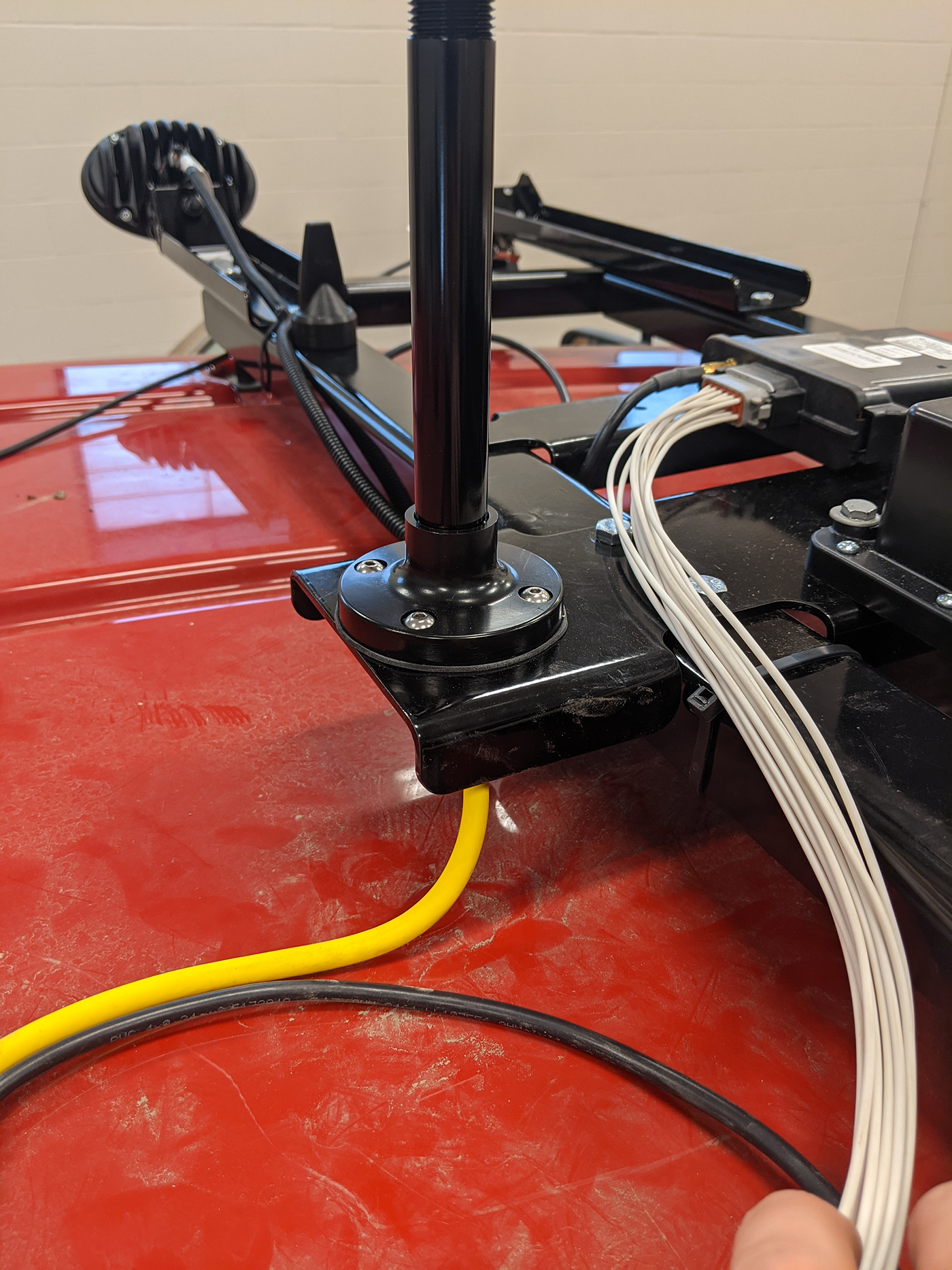
- Mount the beacon flange to the center, left rail behind the rear strut on the antenna bracket.
- Mount a 112° FOV camera (P/N 063-2610-010) on each side camera bracket and secure using four M4 screws per camera.
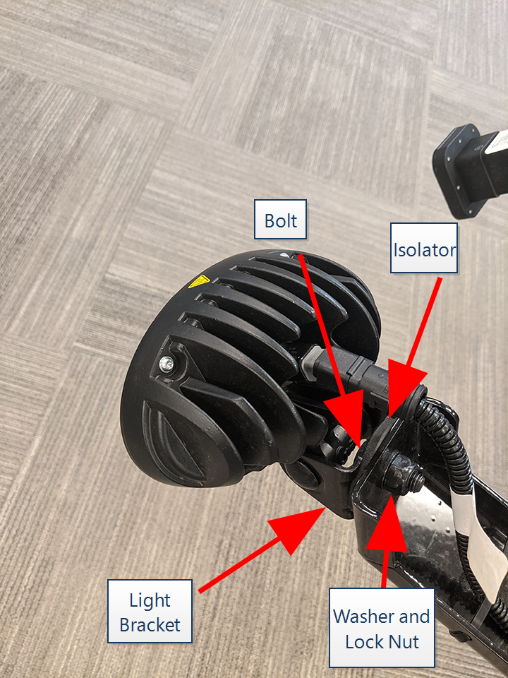
- Use the large mounting bolt, isolator, washer, and lock nut to secure the Grote light (P/N 512-2001-052) to each side light bracket and secure with the provided hardware.
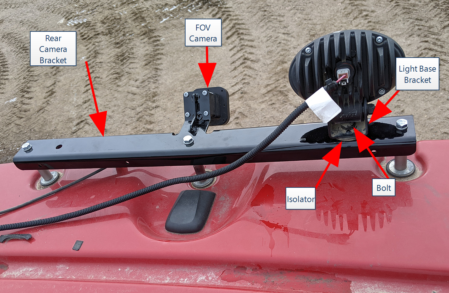
Rear Camera Bracket
-
Mount a 112° FOV camera (P/N 063-2610-010) to the rear camera bracket (P/N 116-2610-009) and secure using four M4 screws.
-
Mount the light base bracket to the rear camera bracket with the bolt, isolator, washer and lock nut.
Note: The light may be mounted on either the left or right side of the rear facing camera.
Front Camera Bracket
- Mount the adjustment bracket
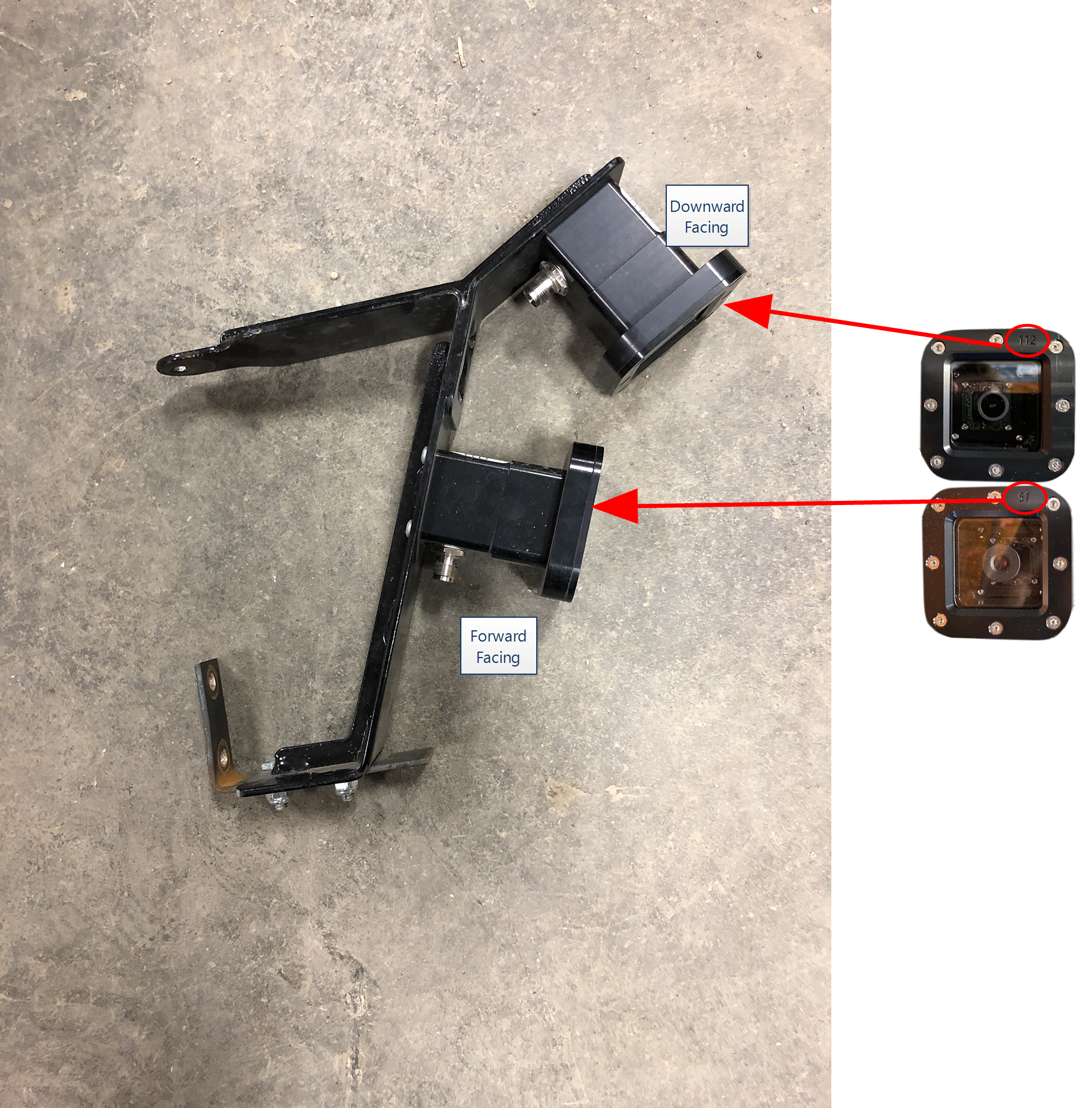
- Mount a 112° FOV camera (P/N 063-2610-010) and 57° FOV camera (P/N 063-2610-016) to the front camera bracket (P/N 116-2610-008) as shown in the image below and secure using four M4 screws.
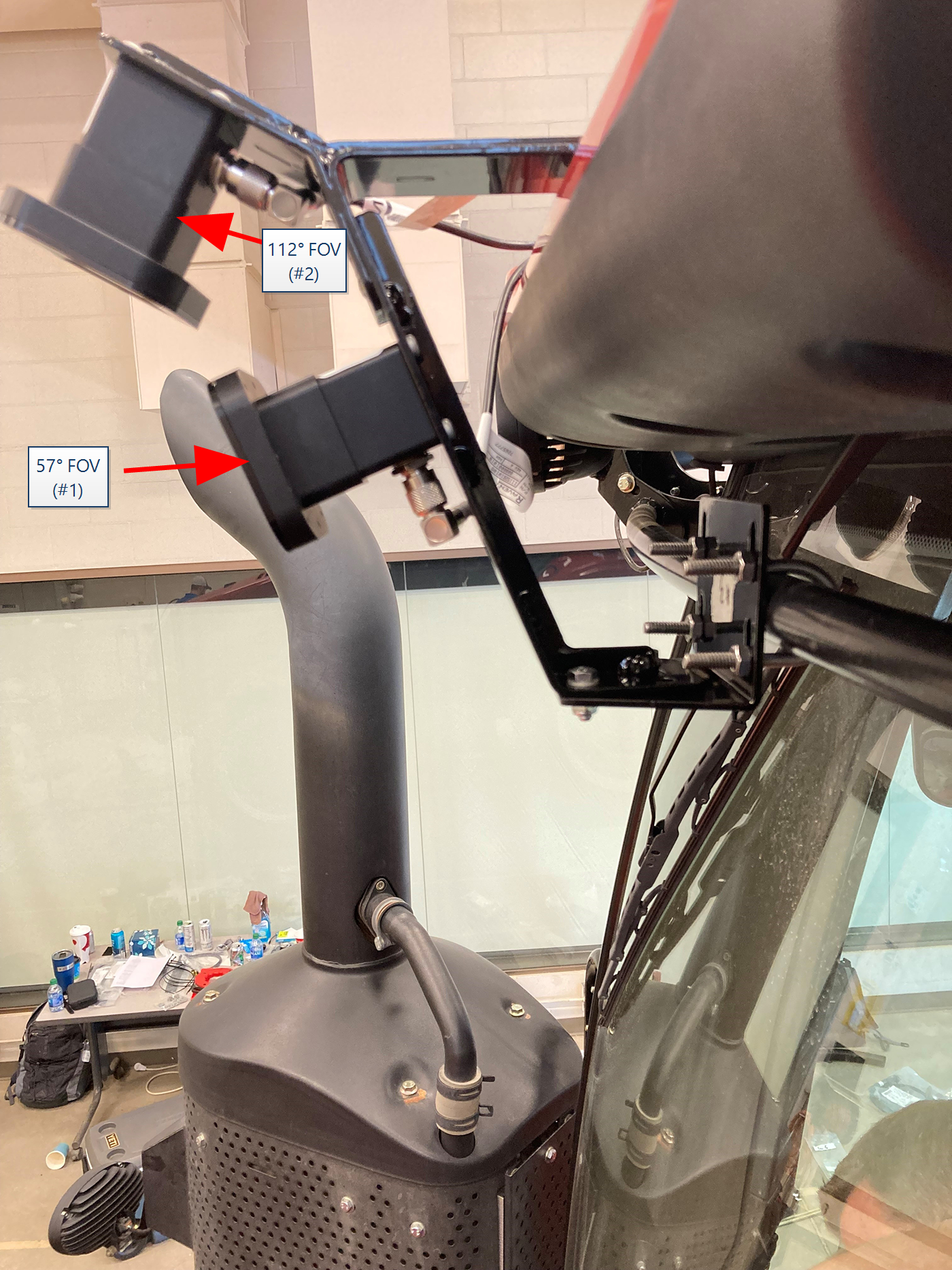
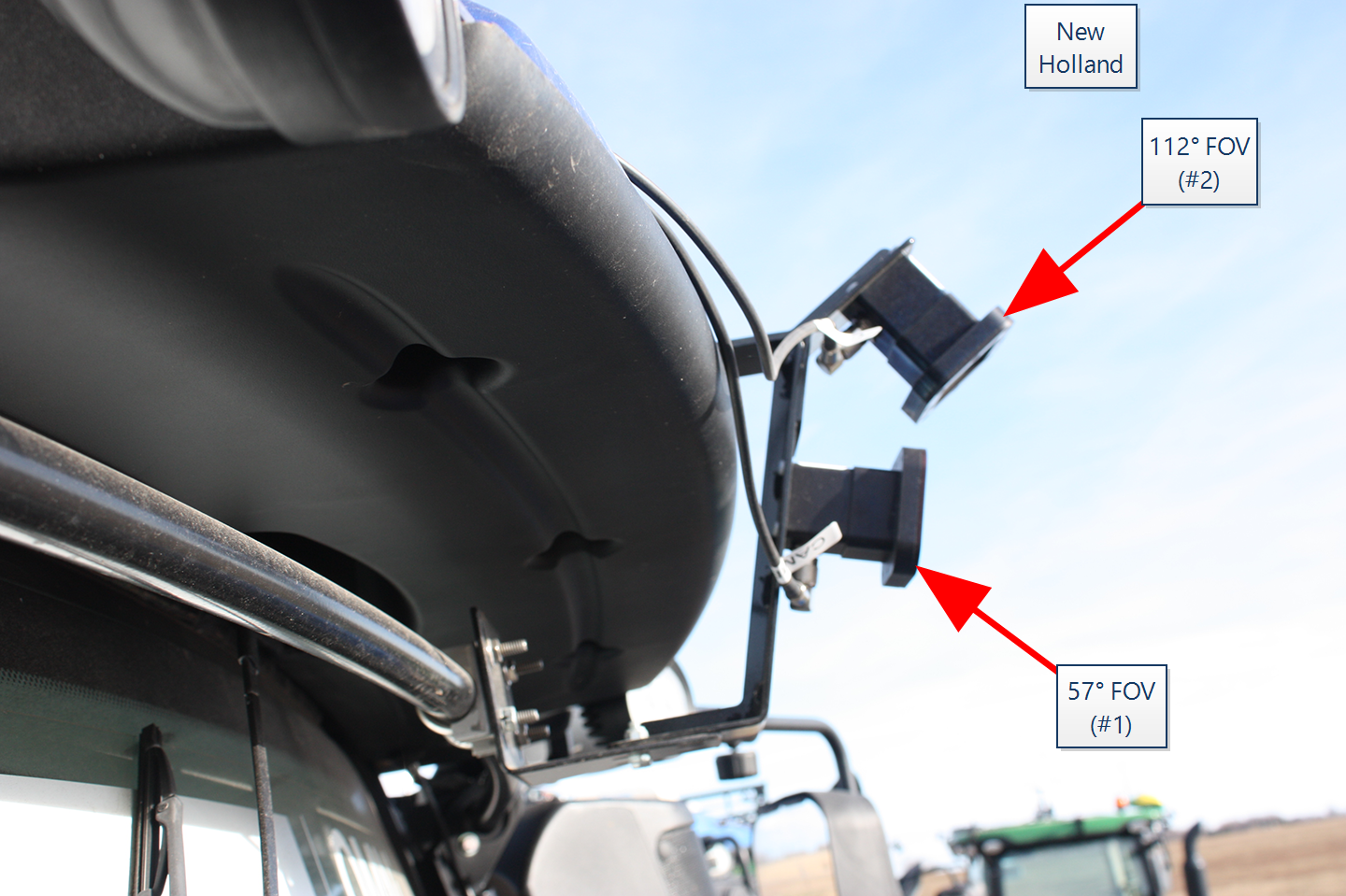
Note: Mount all cameras so that the coaxial port faces toward the ground. The forward facing camera is marked with "57" on the camera housing. The remaining cameras are marked with "112" on the housing.
Connect the RS Lite MCM Cable and Antenna Devices
- Locate the 35-pin bulkhead connector labeled X3M on the RS Lite MCM cable (P/N 115-2610-094).
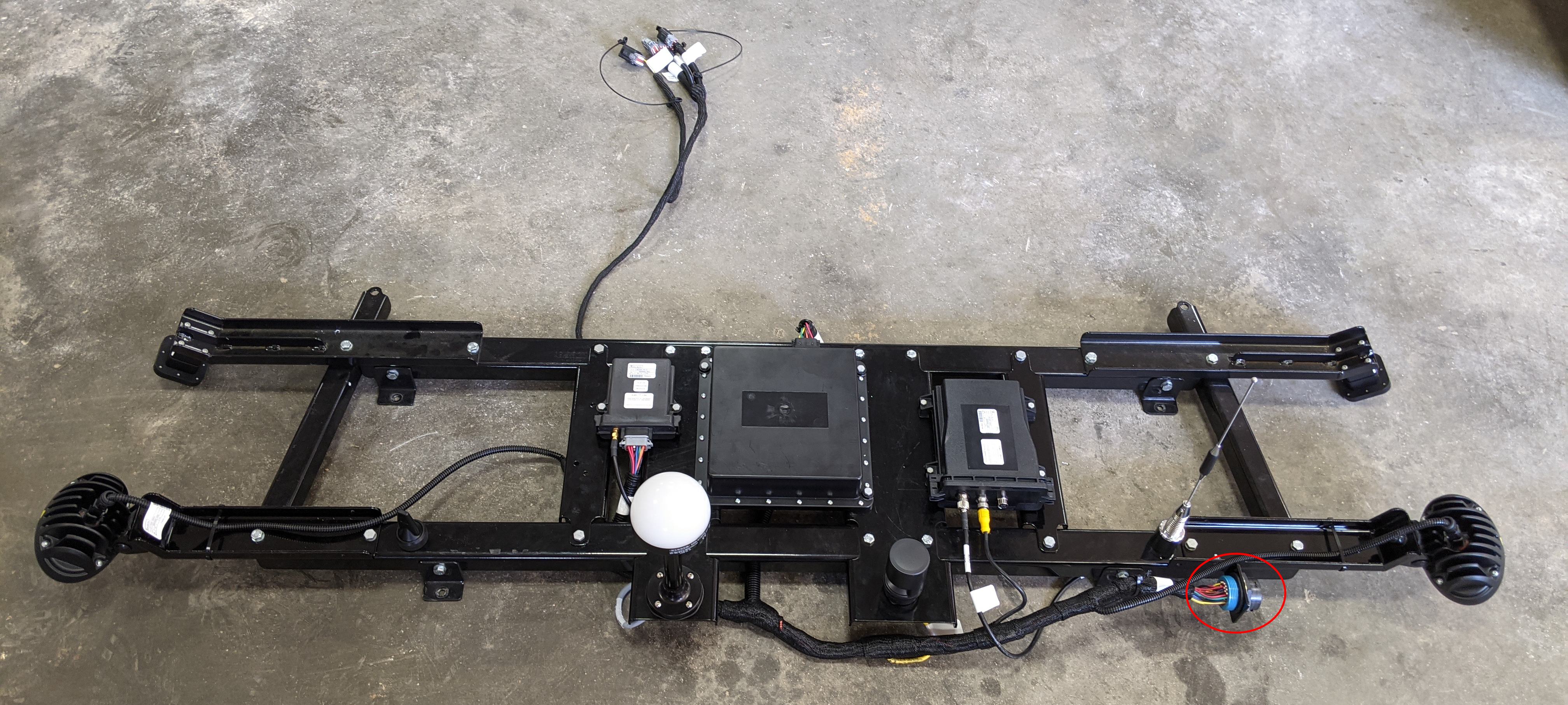
- Fasten the bulkhead connector to the bulkhead bracket mounted to the antenna bracket.
Note: The main MCM harness (P/N 115-2610-092) will connect to the RS Lite MCM bulkhead connector on the cab roof.
- Route the rectangular, 12-pin connector labeled RS Lite underneath the roof bracket to the rectangular port on the RS Lite.
- Route the 4-pin connector labeled J23 HORN to the bottom of the audible alarm mounted on the roof bracket.
- Route and connect the 8-pin connector labeled CA7 to the 8-pin port on the radio.
- Connect the straight end of the radio cable (P/N 115-2610-112) to the radio.
- Route and connect the 90° connector to the bottom of the radio antenna.
- Connect the radio Ethernet cable (P/N 420-2002-111) to the radio.
Note: The other end will route to the device plate after the antenna bracket is secured to the cab roof.
- Route the rectangular, 12-pin connector labeled RCU underneath the roof bracket to the port on the RCU.
- Connect the E-Stop cable (P/N 420-2002-108) to the RCU.
- Route the E-Stop cable to the E-Stop antenna mounted to the roof bracket.
- Route the remaining 2-pin connectors to the left and right light brackets and connect to the perception lights.
Note: The remaining connectors labeled RTK
Real-time Kinematic, AUX PWR, ROOF BULKHEAD, and the TRIMBLE 372 PORT A and PORT B will connect to the roof or devices on the roof. - Continue to the Install the Antenna Bracket to mount the bracket on the tractor cab roof.
Last Revised: Jul 2024