Install the Antenna Bracket
|
|
|
|---|---|
|
|
Use caution while working on the cab roof or standing on exterior surfaces. Surfaces may be uneven or slippery and hardware or harnesses may present tripping hazards. Contact a local equipment dealer for additional information or assistance with working on the roof or from an elevated position on a specific make and model machine. |
 warning
- Metric socket set - 5 to 24 mm
- Metric Allen wrenches - up to 8 mm
- Inclinometer or digital level
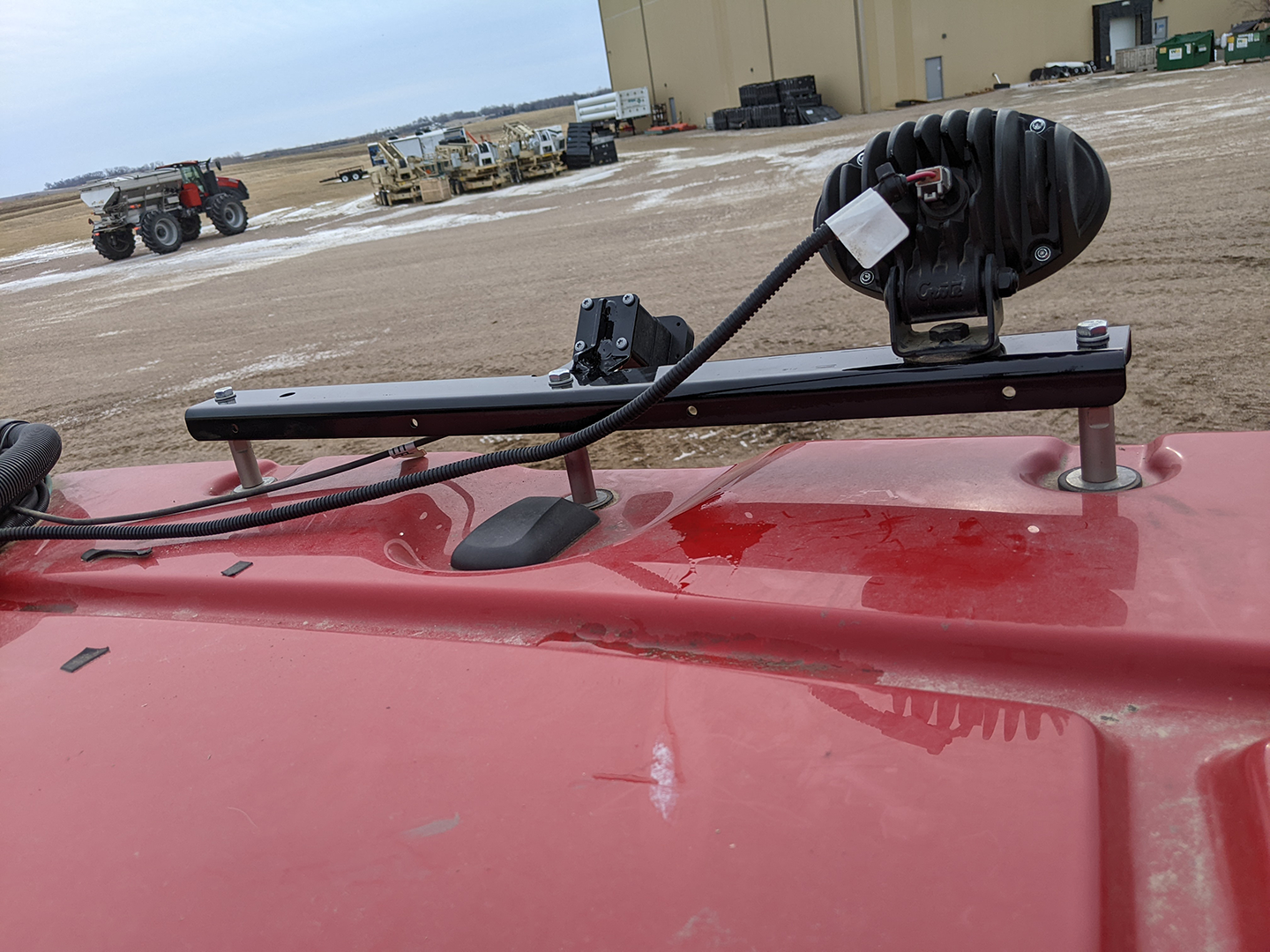
Mount the Front Camera Bracket
- Remove the nut at the front, center of the roof as shown in the following image.
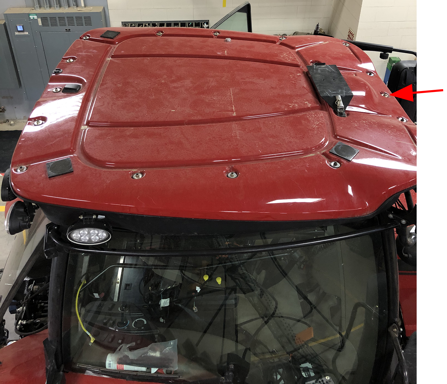
- Use the factory roof nut to secure the front camera bracket to the roof.
- Use the supplied round u-bolt (P/N 107-0172-738) and 1/4 in. nuts to secure the front camera bracket to the bar just under the cab roof.
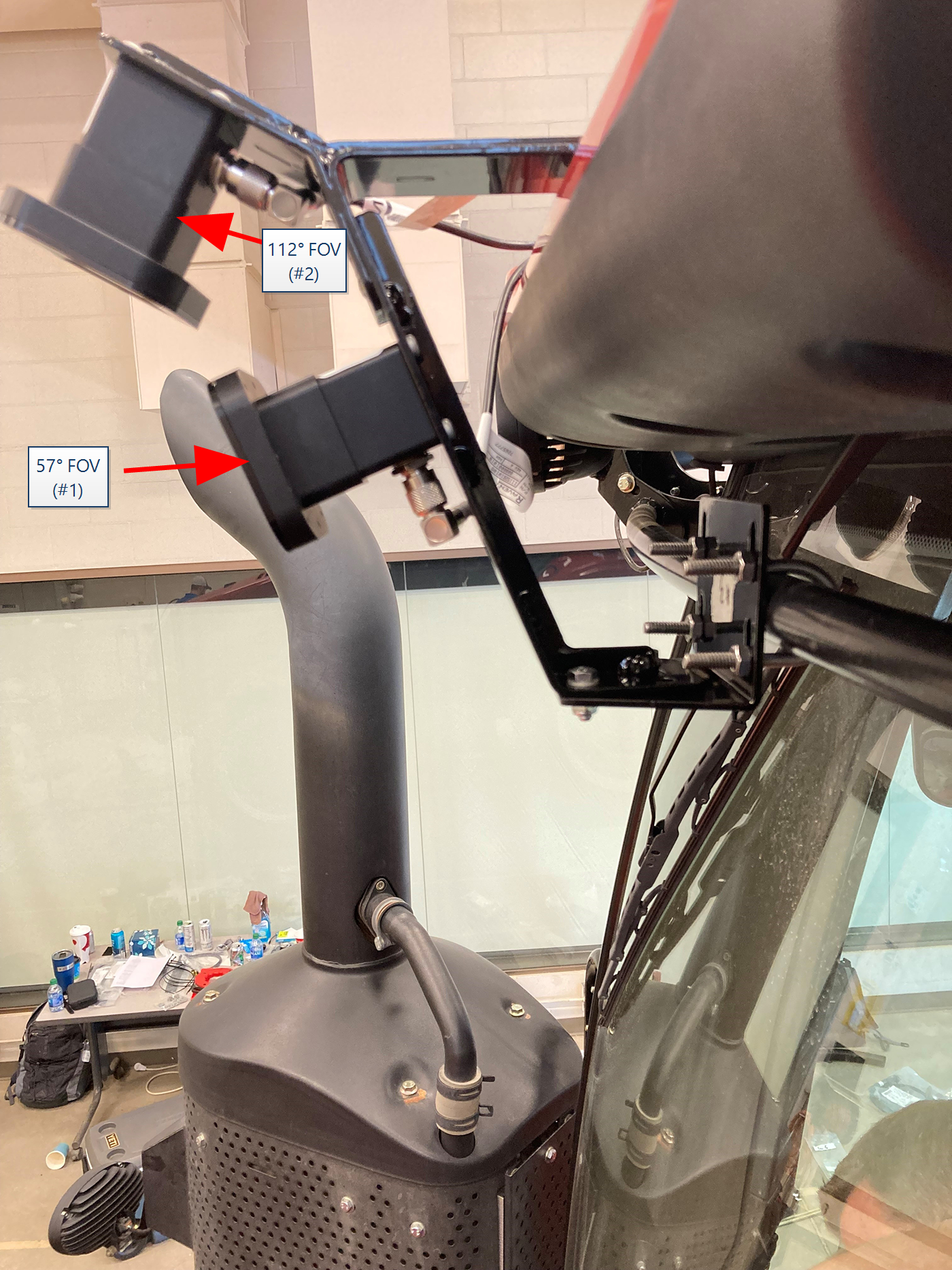
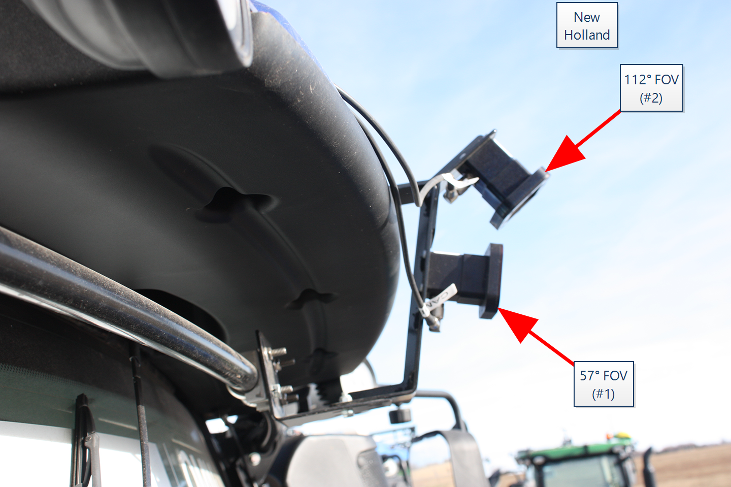
- Use an inclinometer or digital level to measure the front face of the forward facing camera.
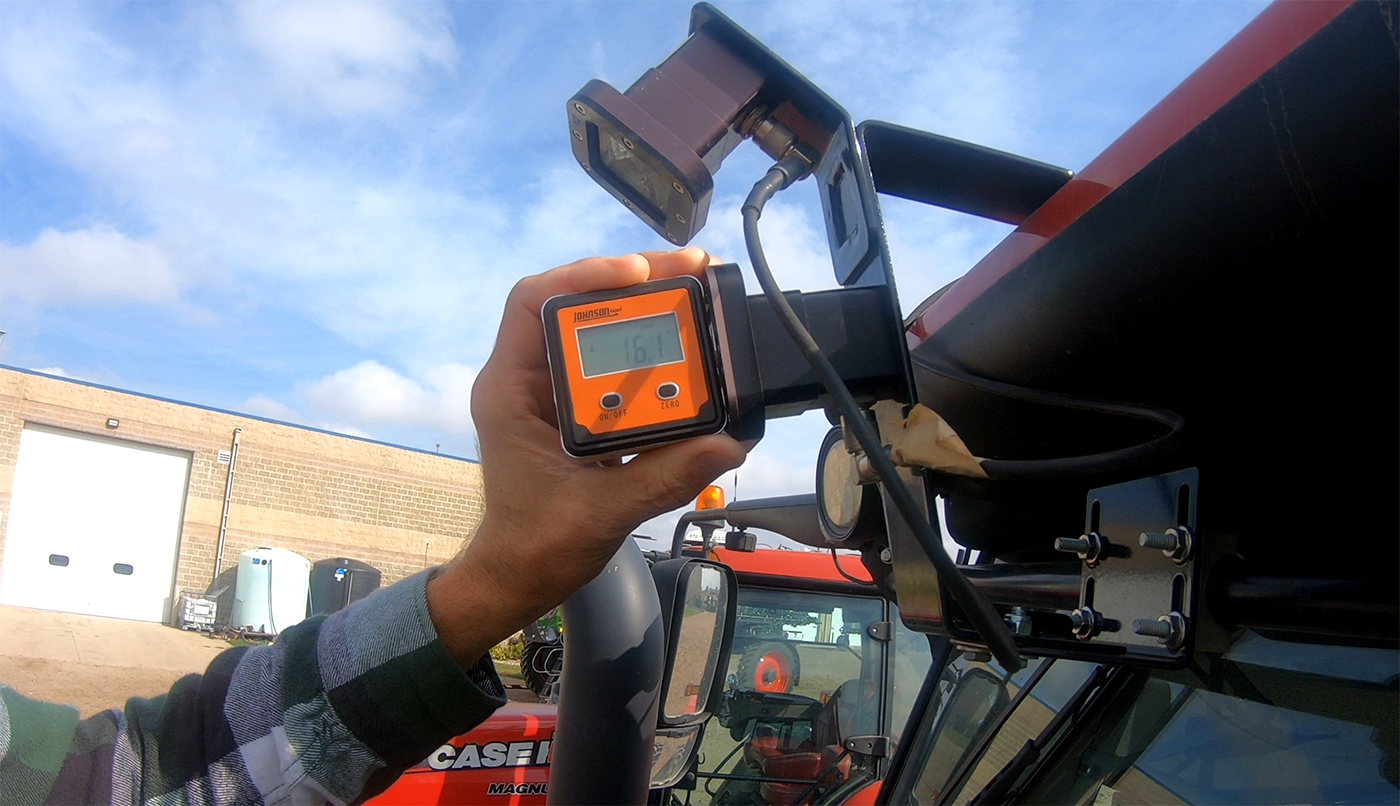
- Use the adjustment bracket to set and secure the forward facing camera at 16° (± 0.5°) from vertical.
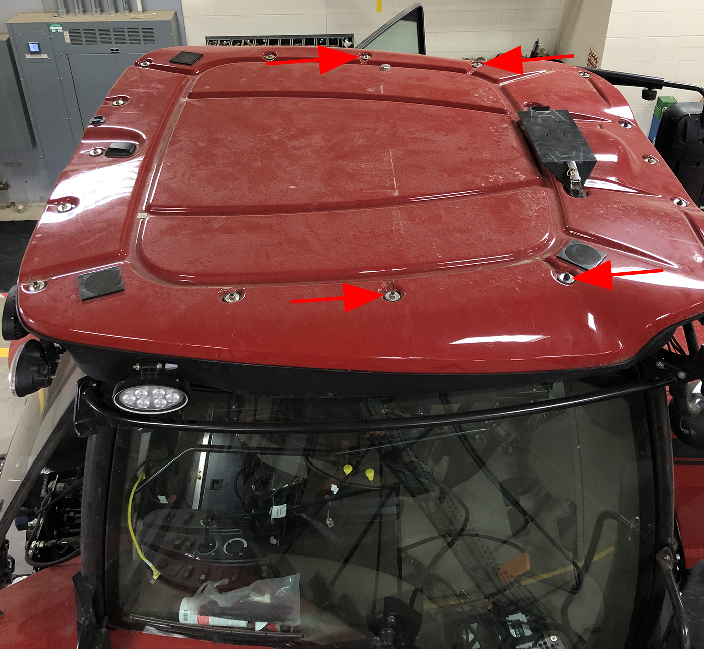
Mount the Rear Camera Bracket
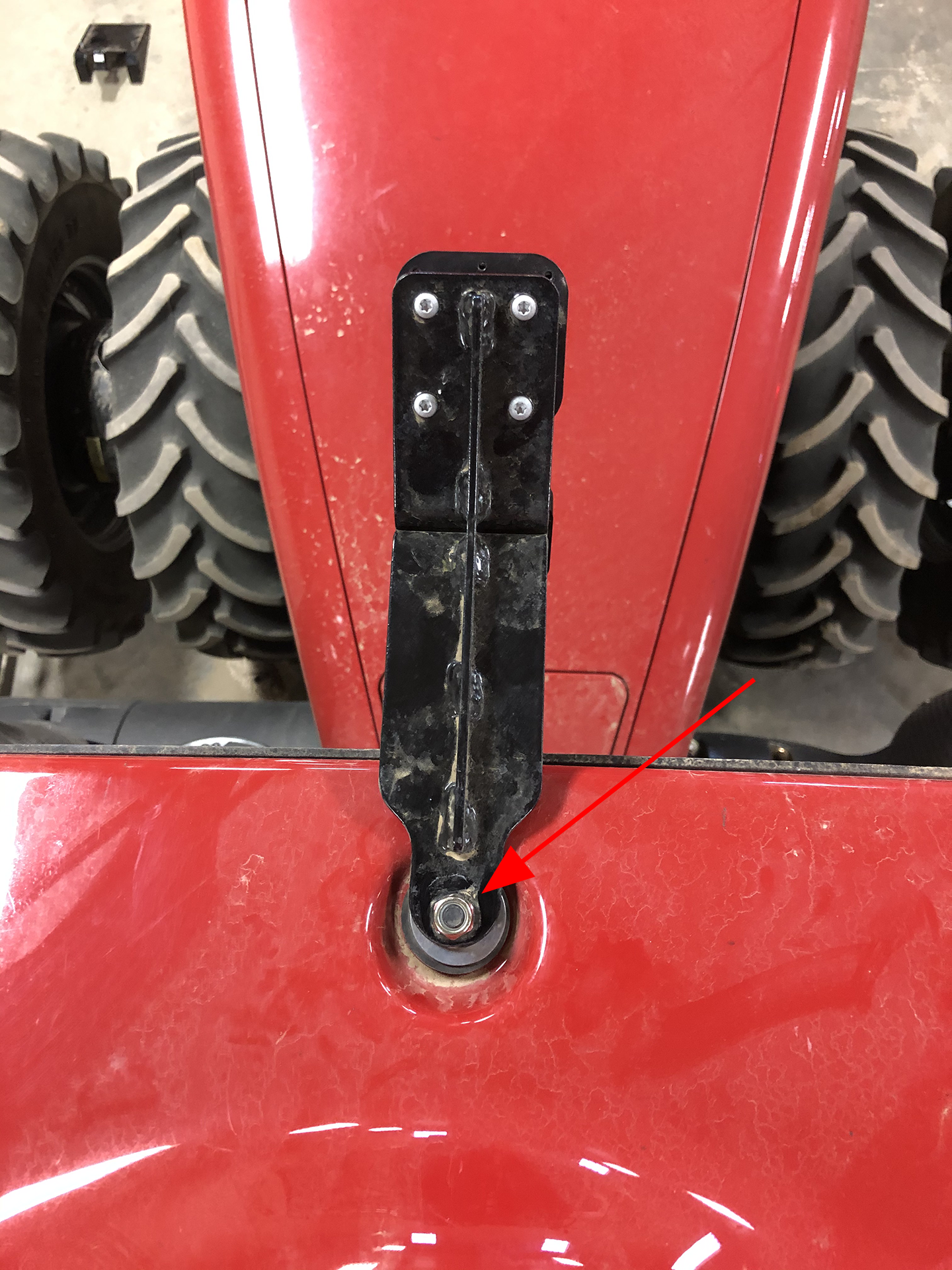
- Remove the nuts from the roof at the locations shown in the following image.
Note: Reuse the factory washers in each location.
- For Case IH Magnum tractors thread a "rear" standoff (P/N 107-2610-032) onto the left and right locations and two washers and a "front" standoff (P/N 107-2610-033) onto the center location.
Note: The two washers are intended to ensure a snug fit with the rear camera bracket.
-
For the New Holland T8 tractor thread a "80 mm" standoff (P/N 107-2610-035) on each location.
- Set the rear camera bracket onto the standoffs and secure with the provided M6 hardware.
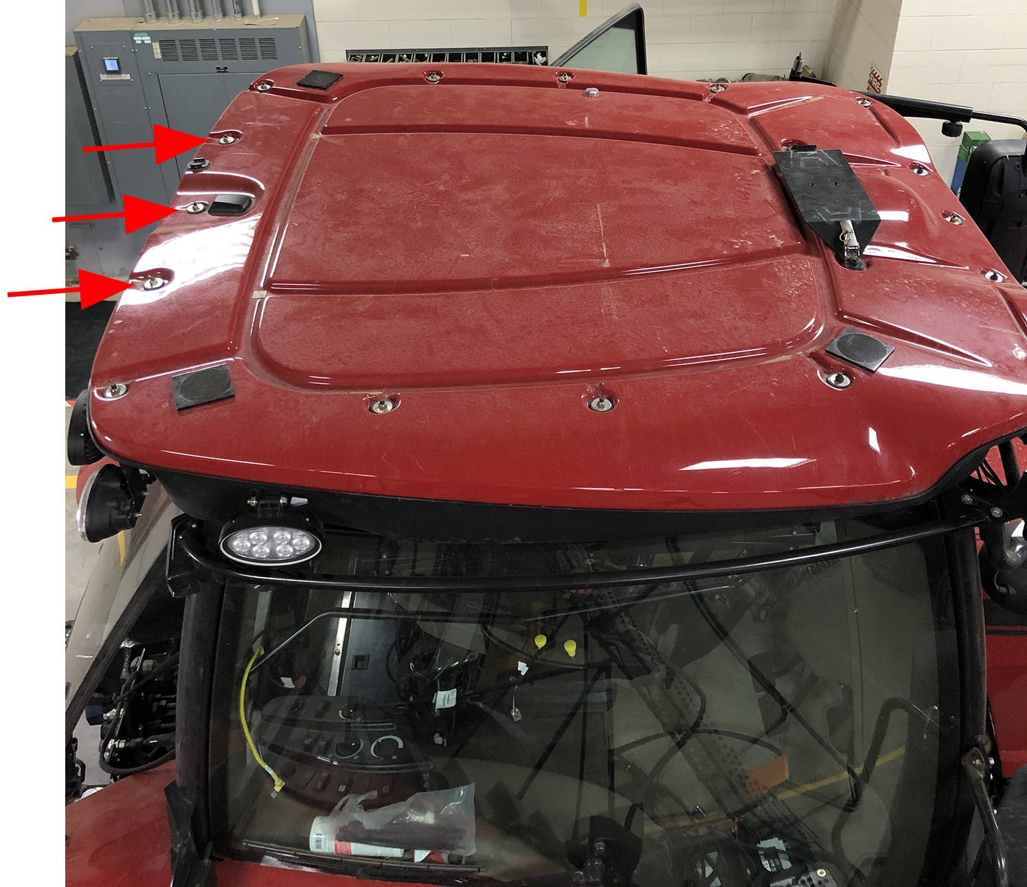
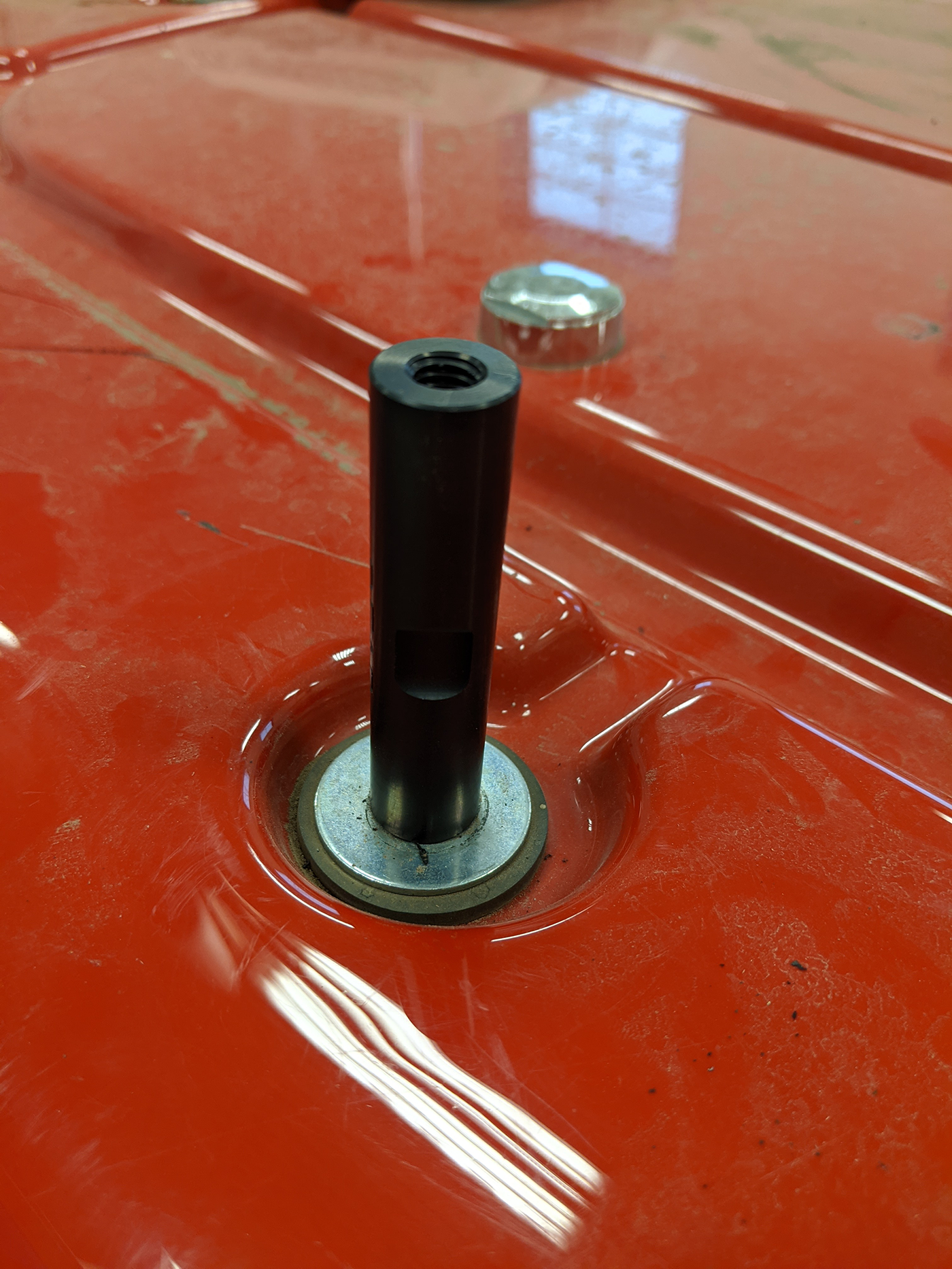
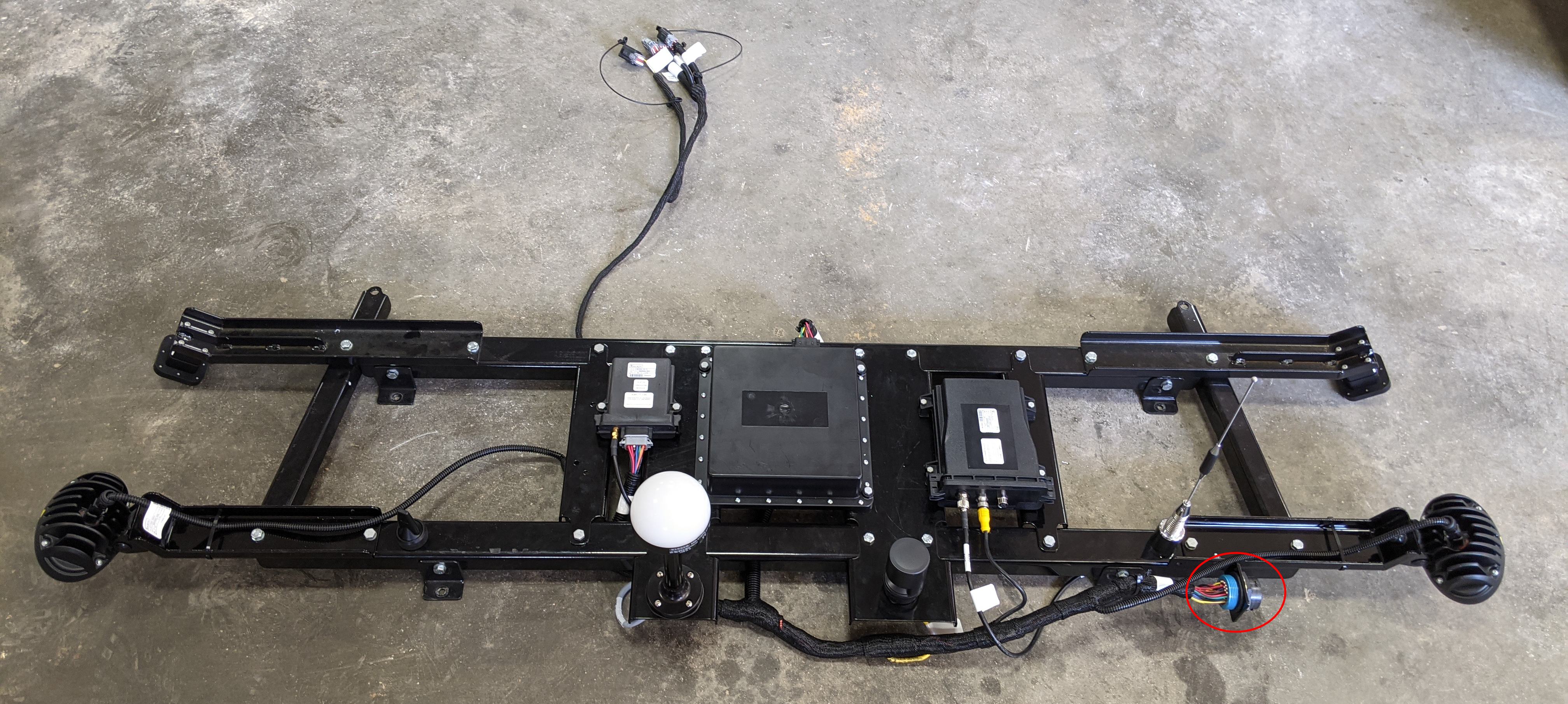
Mount the Main Antenna Bracket
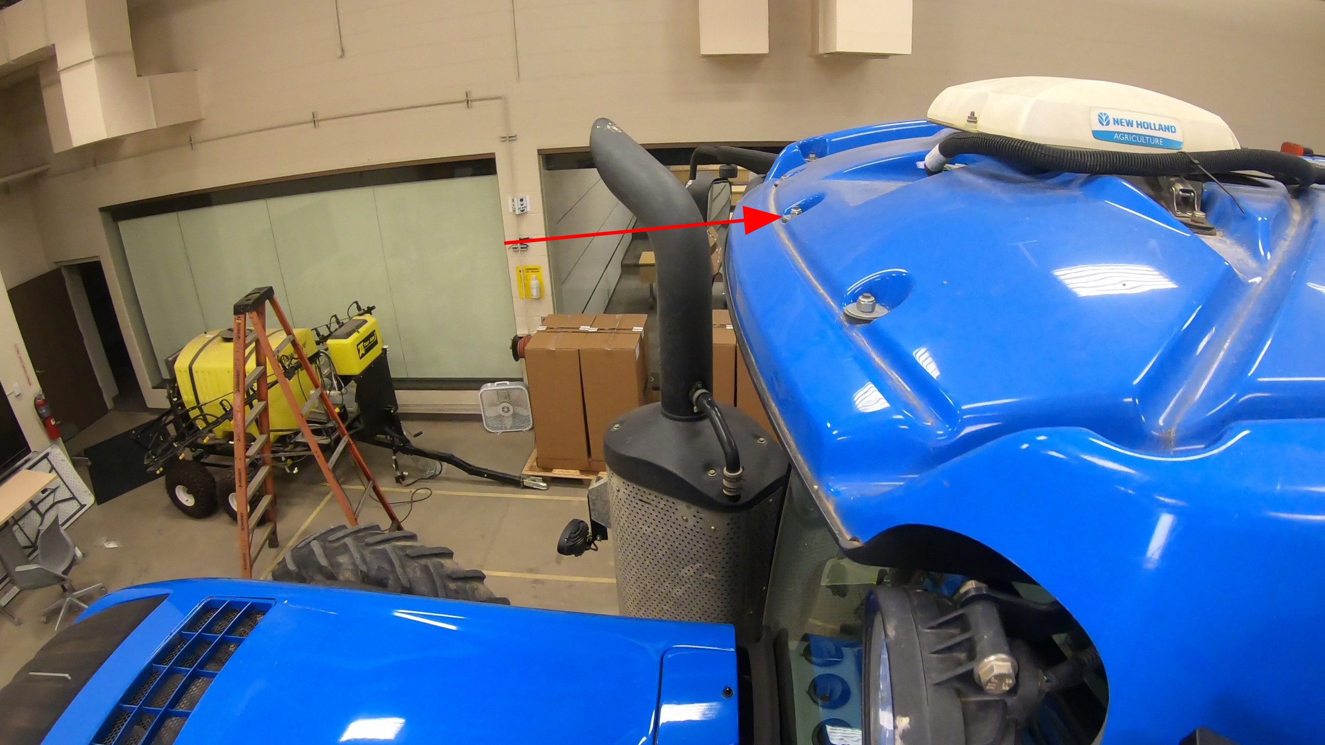
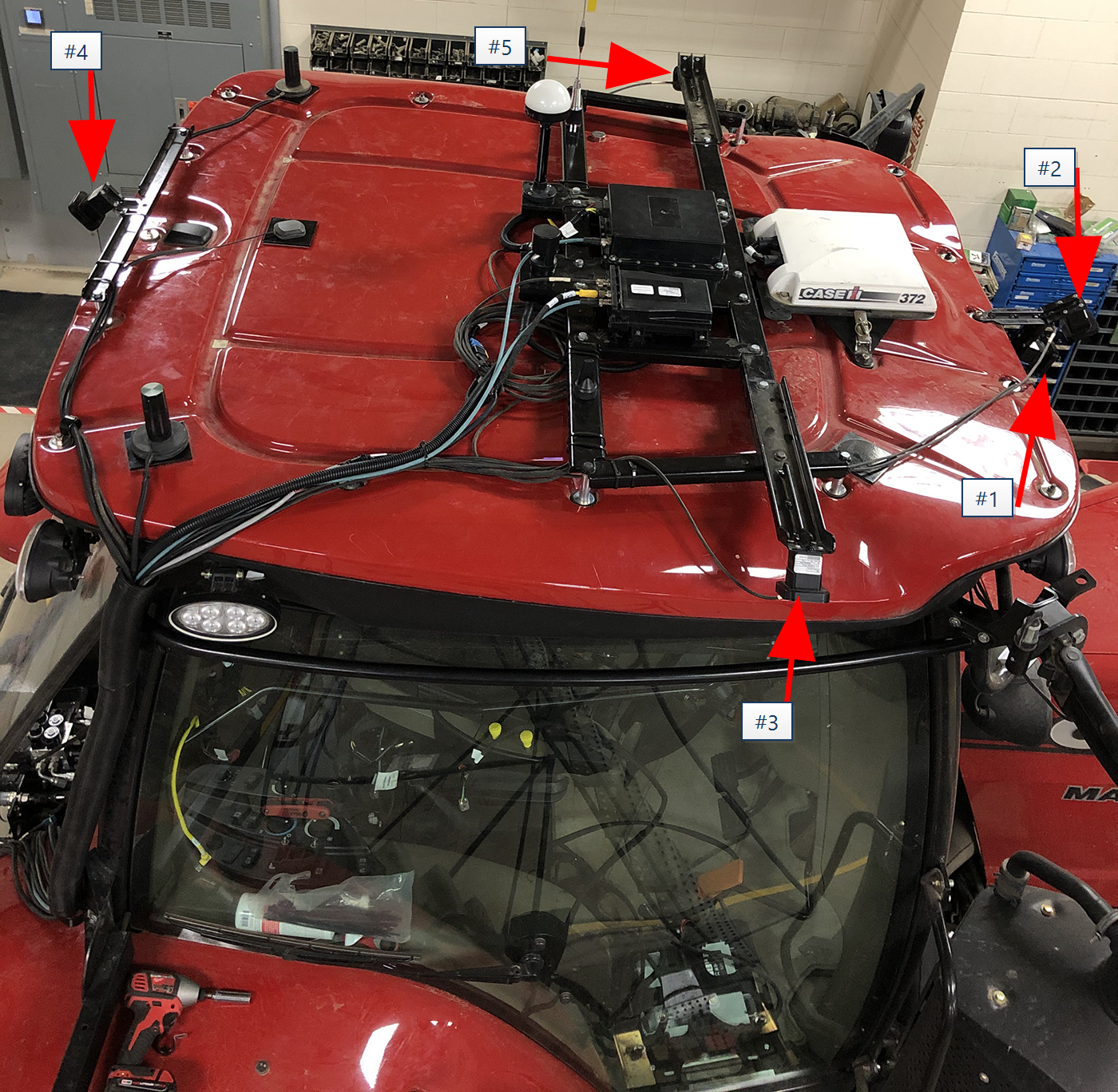
- Remove the nuts from the roof at the locations shown in the following image.
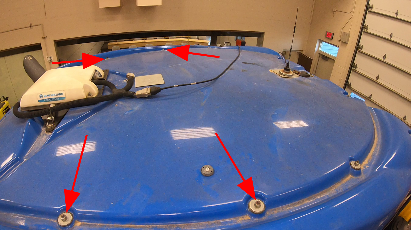
Note: Reuse the factory washers in each location.
- For the Case IH Magnum thread a "front" standoff (P/N 107-2610-033) onto the two locations at the front of the cab roof and a "rear" standoff (P/N 107-2610-032) onto the remaining two locations shown.
-
For the New Holland T8 thread a "90 mm" (P/N 107-2610-034) standoff onto the two front locations on the cab. Thread a "80 mm" (P/N 107-2610-035) onto the two rear location on the cab.
- Carefully lift the antenna bracket assembly onto the roof and set it onto the standoffs. Align the standoffs with the holes in the antenna bracket and secure the bracket to the standoffs with the provided M8 hardware.
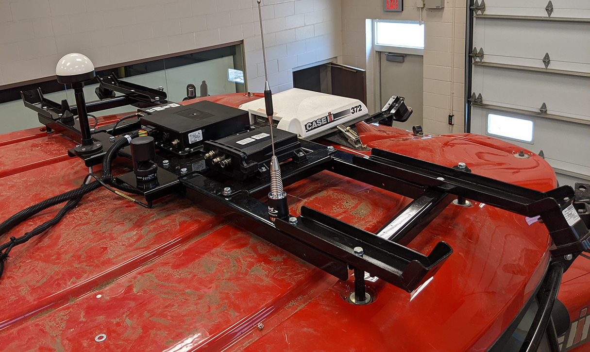
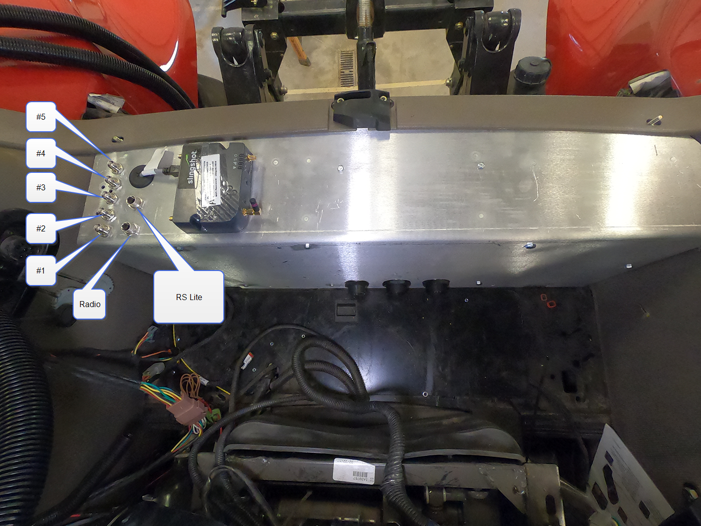
Connect the main and RS Lite MCM Cables
- Locate the round, 35-pin connector labeled X3F on the main MCM cable and connect it to the mating bulkhead connector on the main antenna bracket.
- Locate the 2-pin connector labeled X6F LIGHTS on the main MCM cable and connect it to the perception light on the rear bracket.
- Disconnect the factory 12-pin roof connector from the roof bulkhead at the front of the cab roof.
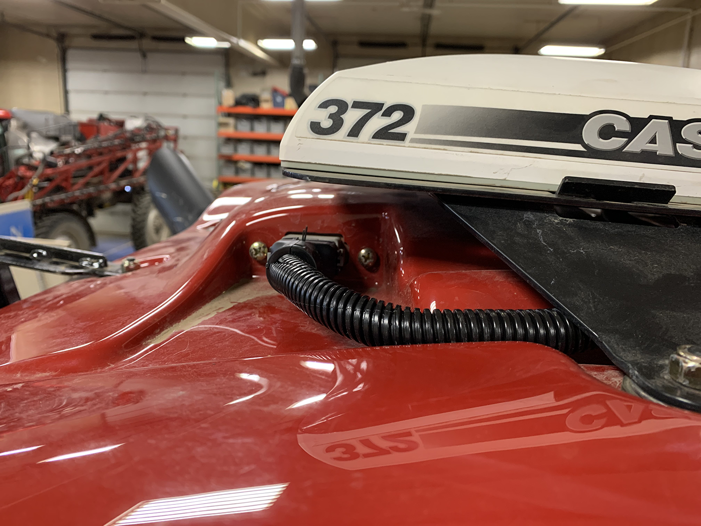
- On the RS Lite MCM cable (P/N 115-2610-094), locate the connector labeled ROOF BULKHEAD.
- Route the connector under the receiver bracket and insert the connector into the roof bulkhead port.
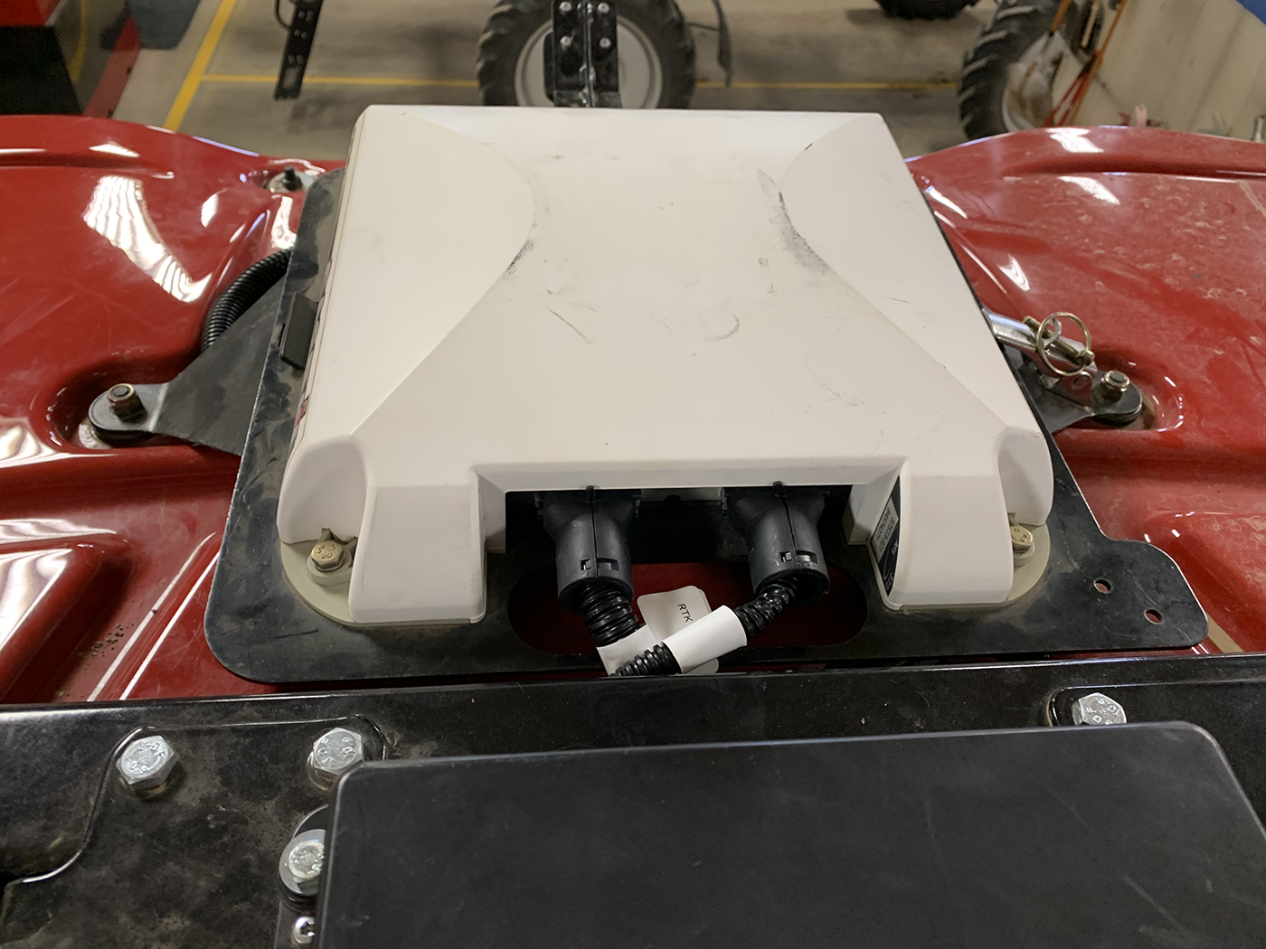
- Disconnect the factory connectors from the GPS receiver and remove the factory harness from the tractor.
- Route and connect the 12-pin connectors labeled TRIMBLE 372 PORT A and PORT B to the GPS receiver ports.
- Connect the Ethernet cable (P/N 420-2002-110) to the Ethernet port on the RS Lite.
- Route the Ethernet cable (P/N 420-2002-110) to the right, rear corner of the cab roof, through the grommet in the lower, right corner of the rear window, and connect it to the RS Lite Ethernet port on the device plate.
- Connect the Ethernet cable (P/N 420-2002-111) to the Ethernet port on the radio.
- Route the Ethernet cable to the right, rear corner of the cab roof, through the grommet in the lower, right corner of the rear window, and connect it to the radio Ethernet port on the device plate.
- If Slingshot® RTK
 Real-time Kinematic corrections will be used with the OMNiDRIVE™ system, connect the AFS 372 to modem adapter cable (P/N 115-2610-115) to the 12-pin connector labeled RTK on the RS Lite MCM cable.
 - Route the cable to the Slingshot® Field Hub and connect to the serial port on the modem.
Note: If receiving RTK corrections via a radio source (e.g. CORS network, traditional base station, etc.), leave the RTK connection on the RS Lite MCM cable capped and do not use the AFS 372 to modem adapter cable.
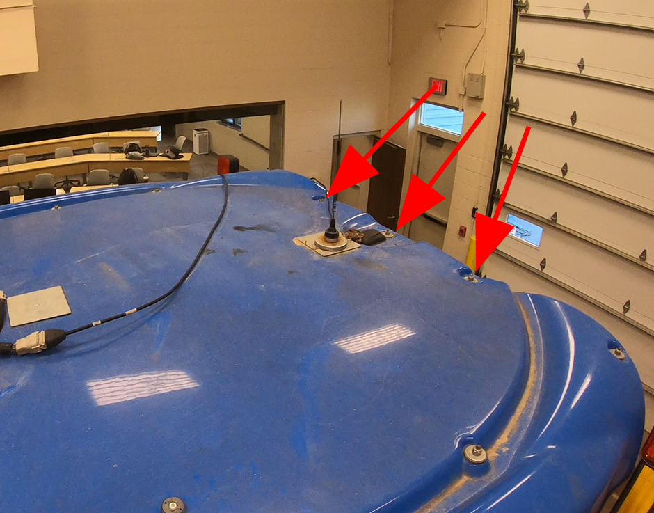
- Refer to the Slingshot® Field Hub manual for additional specifications for the cellular and diversity antennas and the modem GPS antenna.
Example of acceptable antenna mounting locations.
- Proceed to the Install the Camera System to complete the OMNiDRIVE™ tractor installation.
Last Revised: Jul 2024