Install the Brake System
|
|
|
|---|---|
|
|
The implement or machine must remain stationary and switched off with booms or implement sections unfolded and supported during installation or maintenance. |
- Metric wrenches
- Metric Allen wrenches - up to 8 mm
Hydraulic System
Populate the Brake Valve
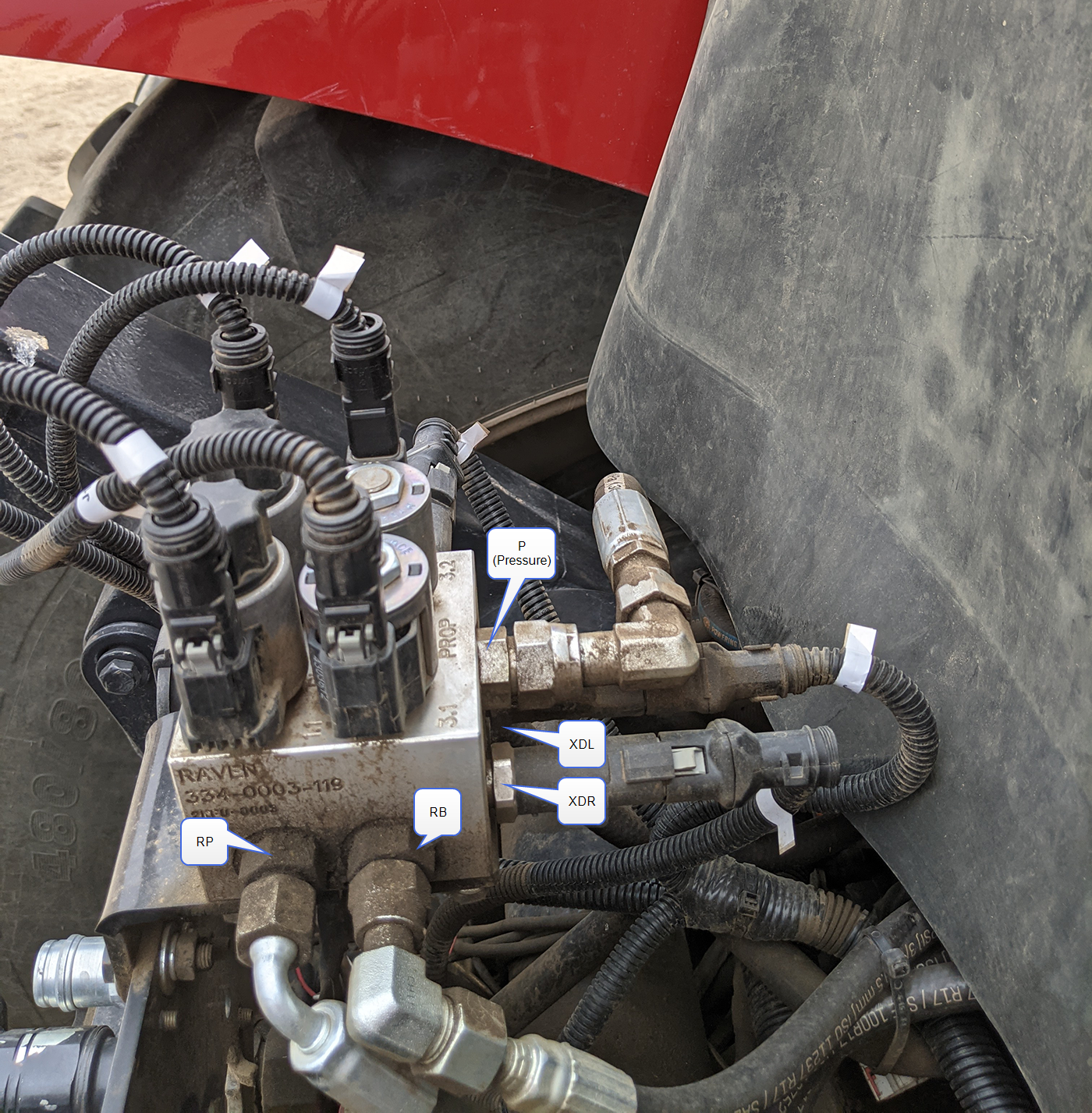
- Thread the following fittings into the hydraulic brake valve (P/N 334-0003-119).
Port Description
Part Number
P Fitting, -8 ORB to -8 ORFS 333-0012-028 LB Fitting, -8 ORB to -6 ORFS 333-0012-199 LP RB RP XDL
Transducer, Pressure (1 to 5 V, 0 to 3,000 PSI) 422-0000-093 XDR XDP 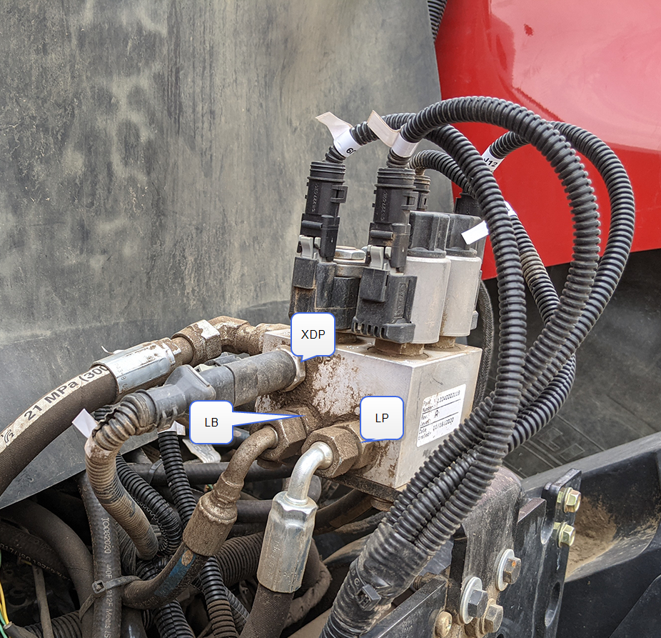
- Tighten fittings to the hydraulic valve.
Mount the Brake Valve
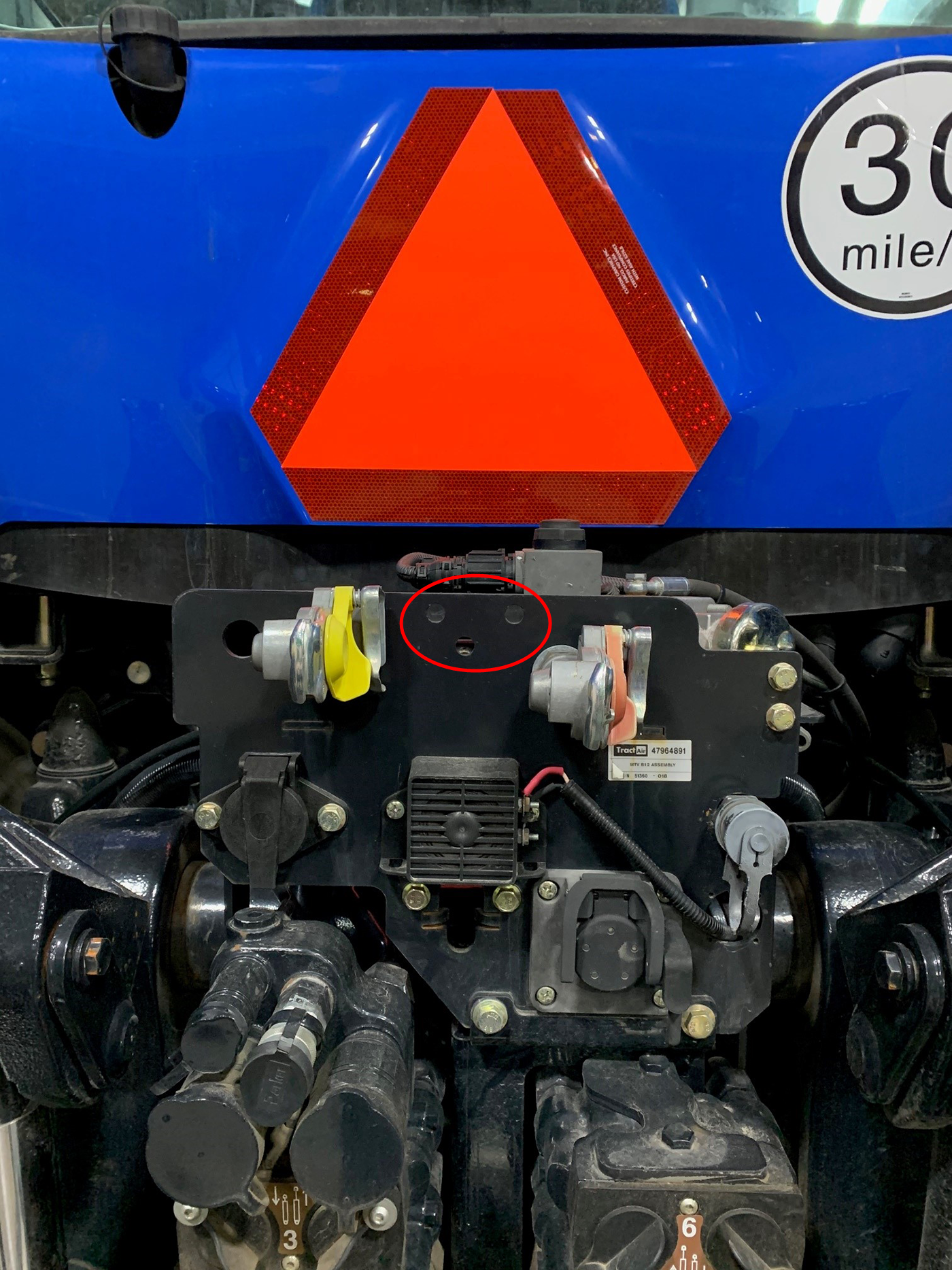
- Check the plate at the back of the cab for predrilled holes for the brake bracket. If holes are not available, use the hydraulic mounting bracket (P/N 107-2610-038) as a template to drill three holes at the position shown below.
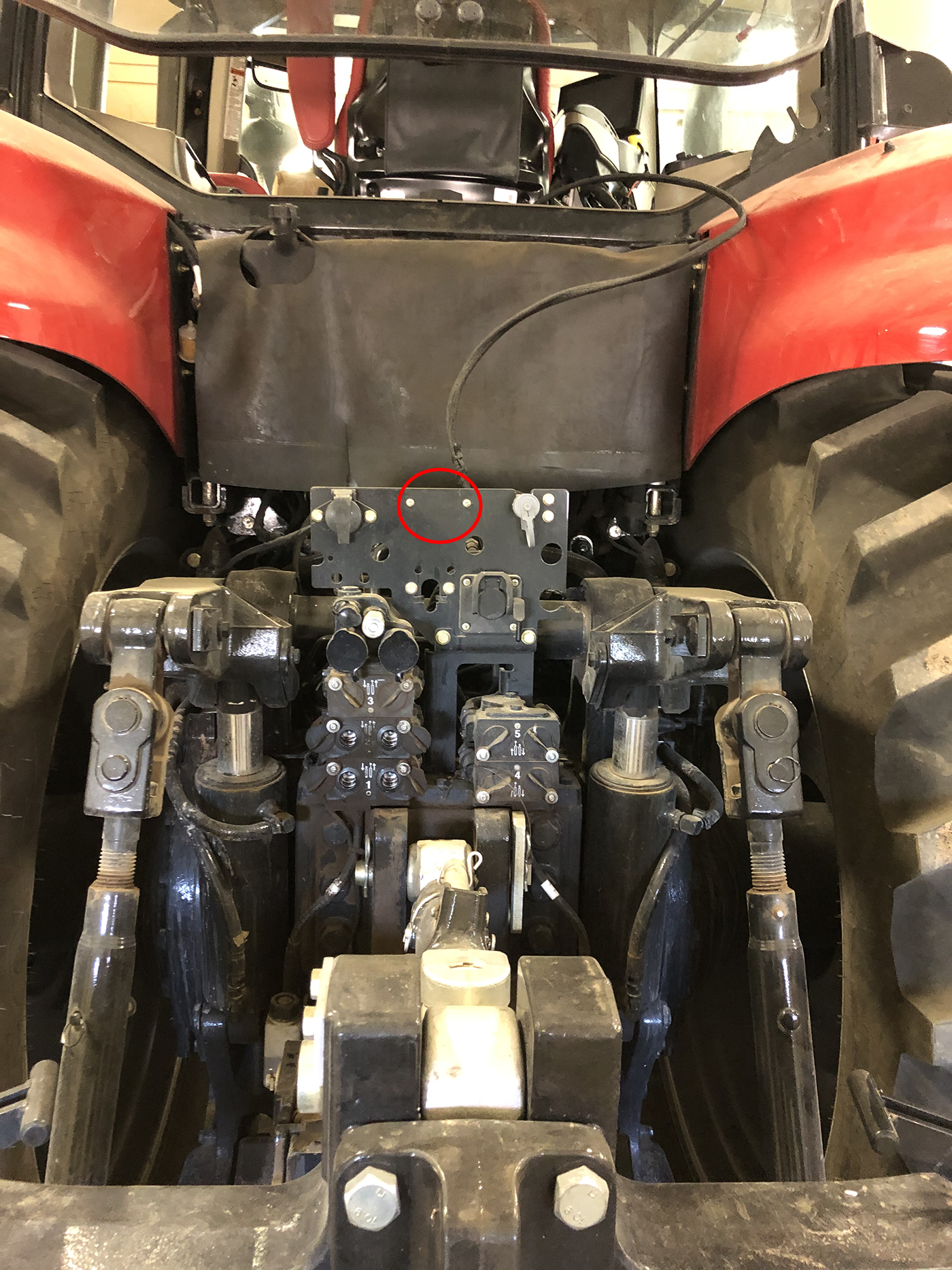
- Using the provided M8 hardware, secure the hydraulic mounting bracket (P/N 107-2610-038) to the bottom of the brake valve.
Note: Orient the bracket so that the hydraulic valve is tucked in behind the cab and the P port is facing toward the front of the tractor. The ports labeled "R" (i.e. RP and RB) should be facing the right side of the tractor and ports labeled "L" (i.e. LP and LB) should be facing the left side.
- Using the provided M10 hardware, secure the hydraulic valve assembly to the IBBC
 Implement Bus Breakaway Connector. Connects to the IBIC on the towed implement. bracket at the rear of the tractor.
Pressure Line
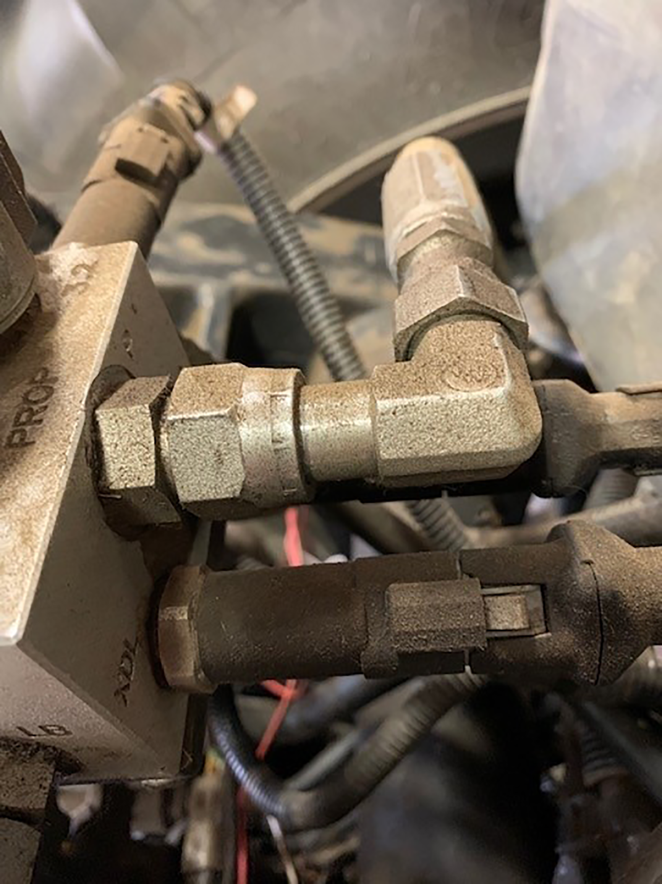
- Locate the pressure port off of the machine hydraulic valve.
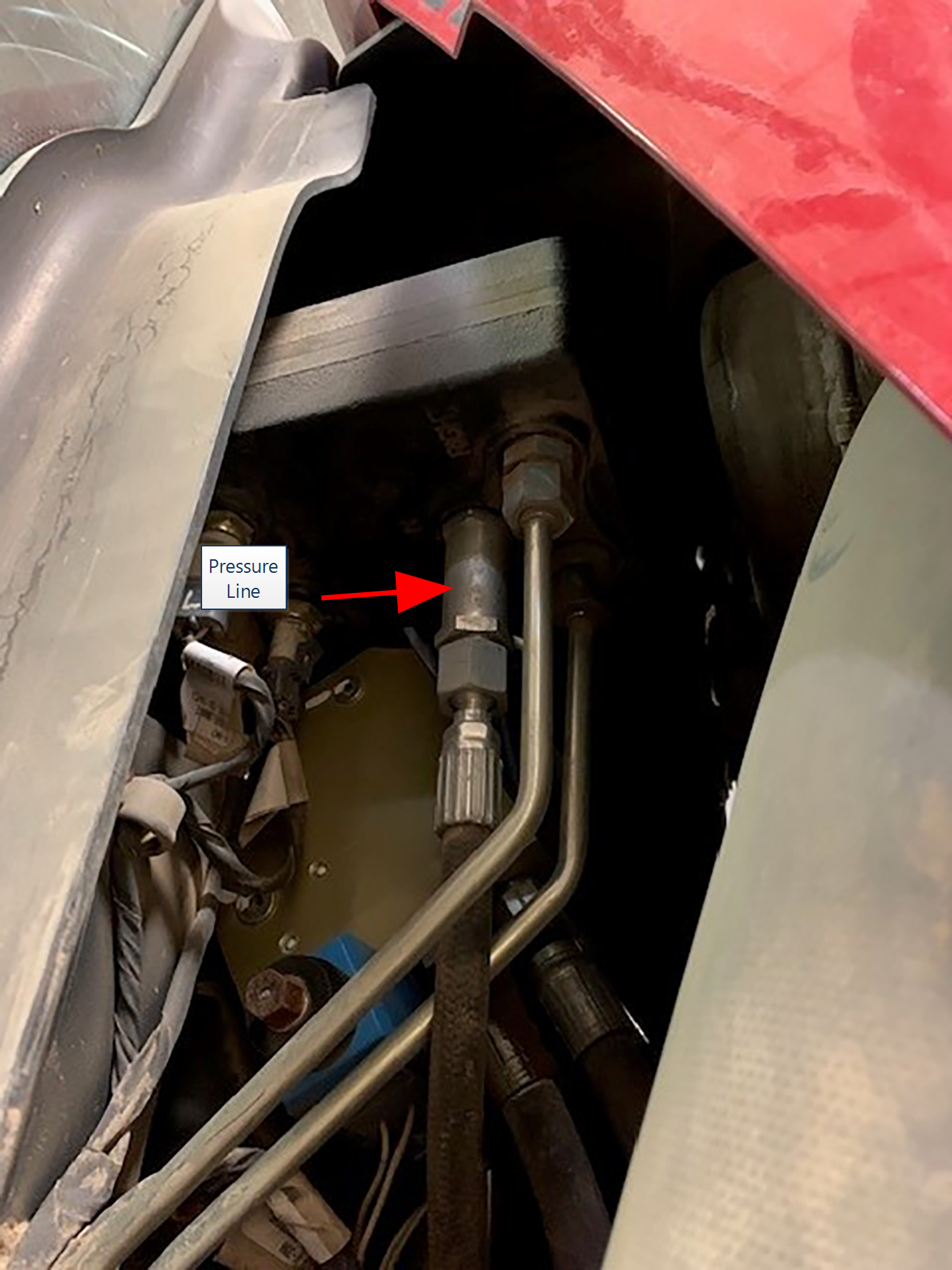
Note: The machine hydraulic valve is located under the hood directly in front of the cab on the right side of the machine.
- Trace the pressure line down to where the flexible line connects to a steel line.
- Disconnect the flexible line from the steel line.
 warning
Hydraulic fluid may be extremely hot and under high pressure. Care should always be taken when servicing or opening a system that has been pressurized. Always wear appropriate personal protective equipment when installing or servicing hydraulic systems.
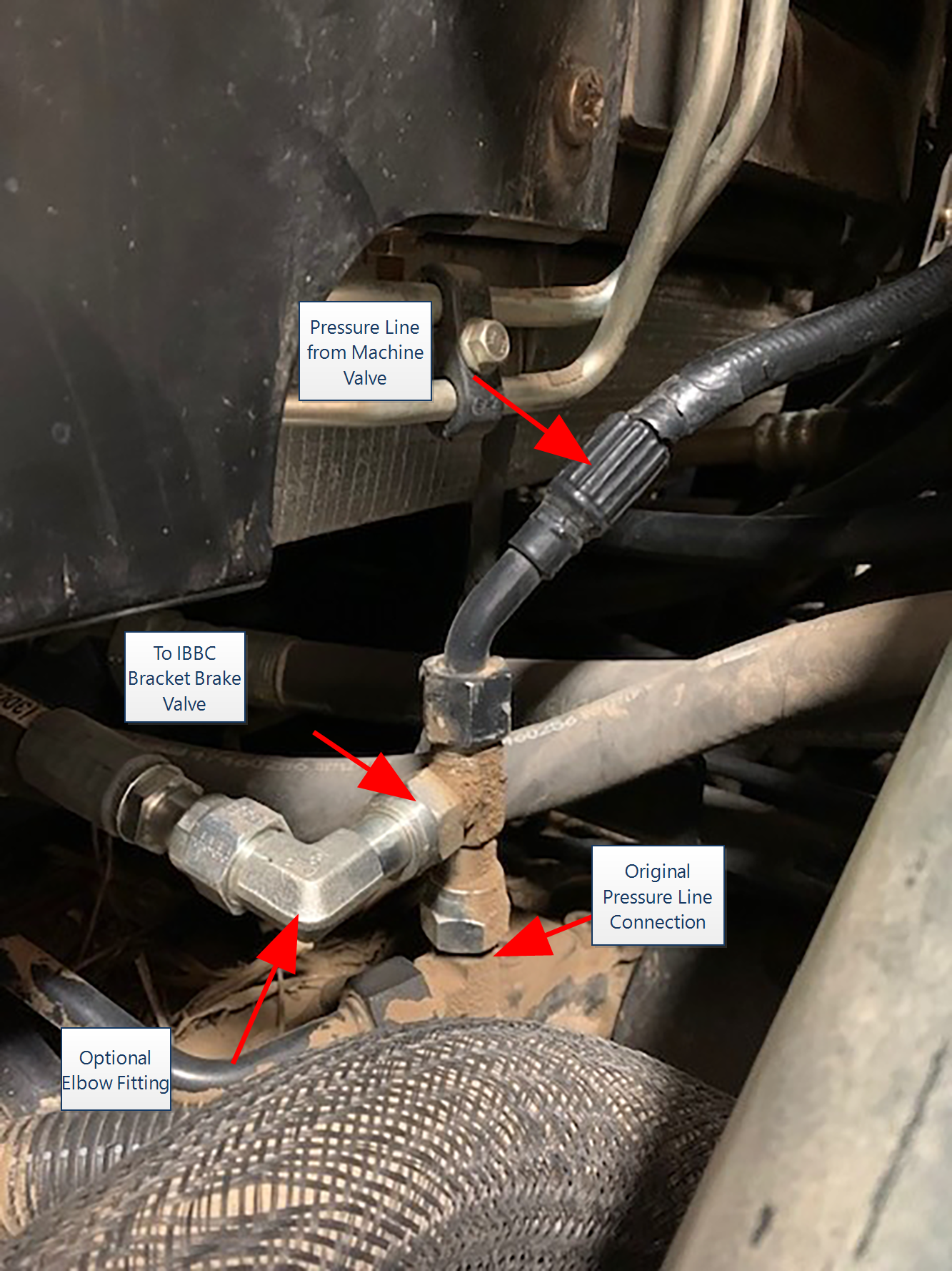
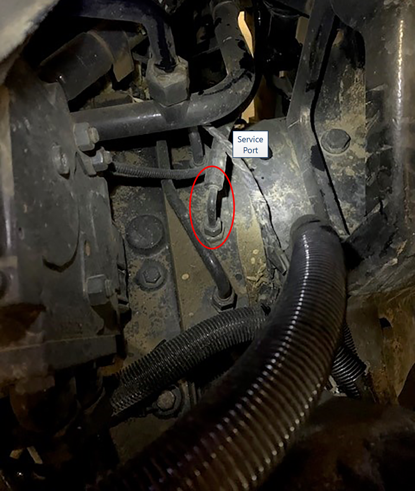
- Install the -8 tee fitting (P/N 333-0012-028) on the steel line and reconnect the flexible line to the opposite end of the tee fitting.
- Connect the supplied hose (P/N 214-1001-217) to the branch of the tee fitting.
Note: Install a -8 90° elbow if needed to make the routing the line easier.
- Route the hose under the cab to the hydraulic brake block mounted to the IBBC bracket at the back of the machine.
- Connect to the pressure line to the P port fitting using a -8 90° elbow.
- Check and tighten all fitting connections on the pressure line to help avoid leaks.
Right Pressure and Brake Lines
-
Differential Global Positioning System is an enhancement to standard GNSS/GPS messages to provide better position accuracy. housing.
- Follow the flexible line to the point where it connects with the steel line just under the cab.
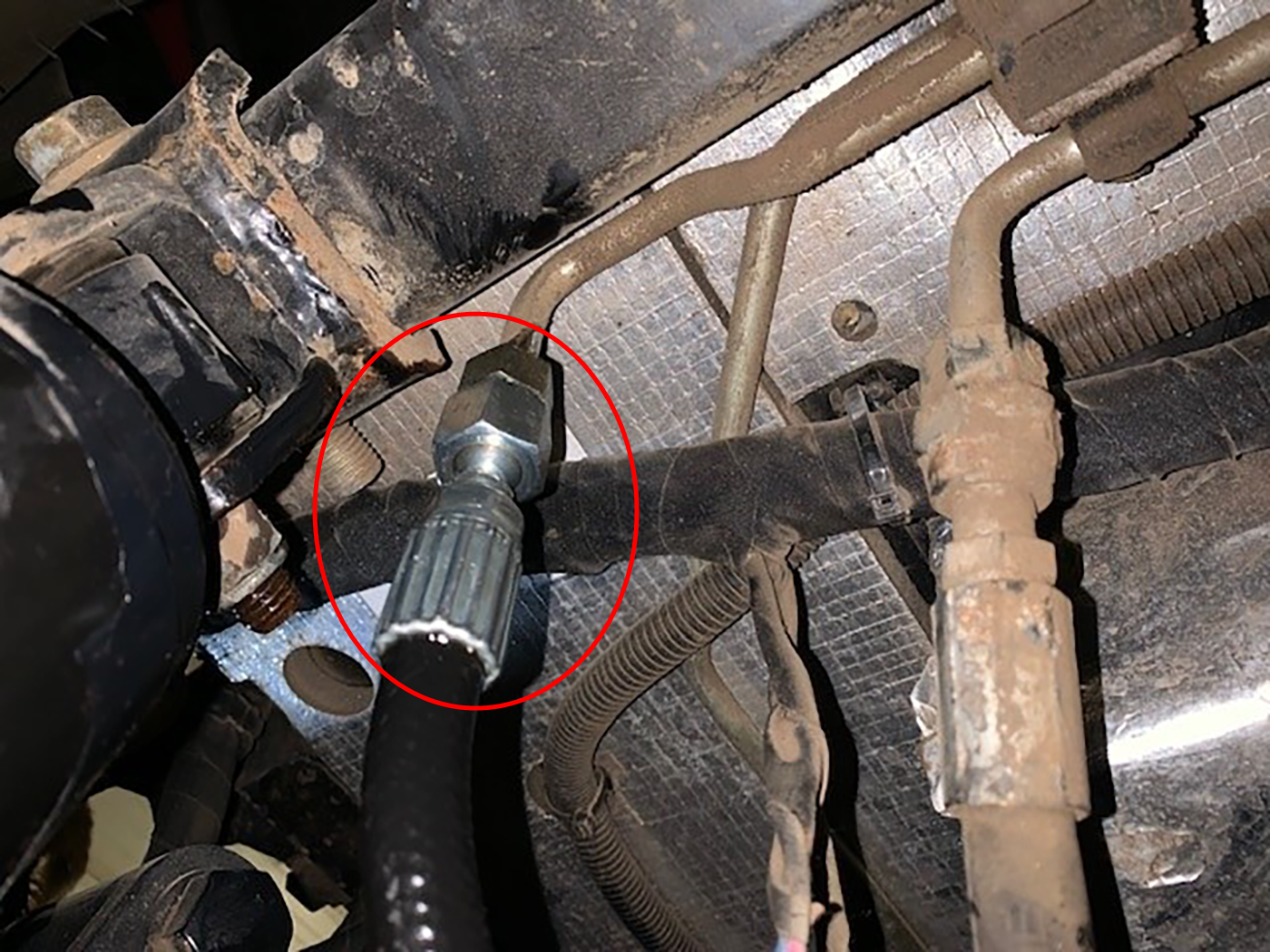
- Disconnect the flexible line from the steel line. warning
Hydraulic fluid may be extremely hot and under high pressure. Care should always be taken when servicing or opening a system that has been pressurized. Always wear appropriate personal protective equipment when installing or servicing hydraulic systems.
- Connect the straight end of the -6 hose (P/N 214-1001-219) to the steel line.
-
- Connect the -6 hose (P/N 214-1001-218) to the flexible line which was previously disconnected from the steel line.
-
- Check and tighten all fitting connections on the pressure line to help avoid leaks.
Left Pressure and Brake Lines
-
- Follow the flexible line to the point where it connects with the steel line just under the cab.
- Disconnect the flexible line from the steel line. warning
Hydraulic fluid may be extremely hot and under high pressure. Care should always be taken when servicing or opening a system that has been pressurized. Always wear appropriate personal protective equipment when installing or servicing hydraulic systems.
- Connect the straight end of the -6 hose (P/N 214-1001-219) to the steel line.
-
- Connect the -6 hose (P/N 214-1001-218) to the flexible line which was previously disconnected from the steel line.
Note: Ensure the pressure transducer on the existing hydraulic line remains installed.
-
- Check and tighten all fitting connections on the pressure line to help avoid leaks.
Electrical Connections
Connect the Brake Valve
- Route the remaining connectors to the brake valve mounted on the rear of the tractor.
- Connect the 3-pin connector labeled INLET PRESSURE J13 to the pressure transducer installed in the XDP port.
- Connect the LEFT BRAKE PRESSURE J14 to the transducer installed in the XDL port.
- Connect the RIGHT BRAKE PRESSURE J15 to the transducer installed in the XDR port.
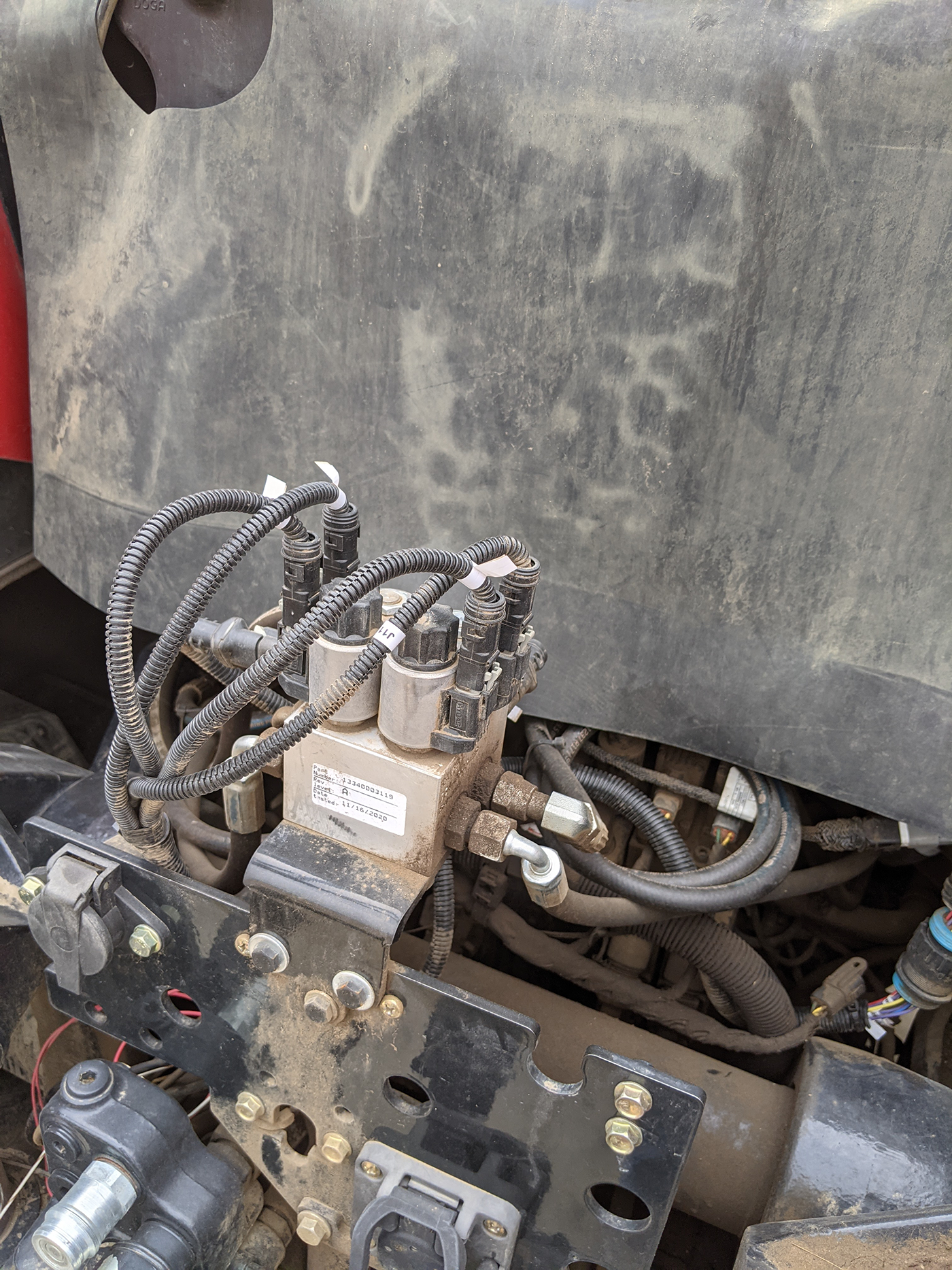
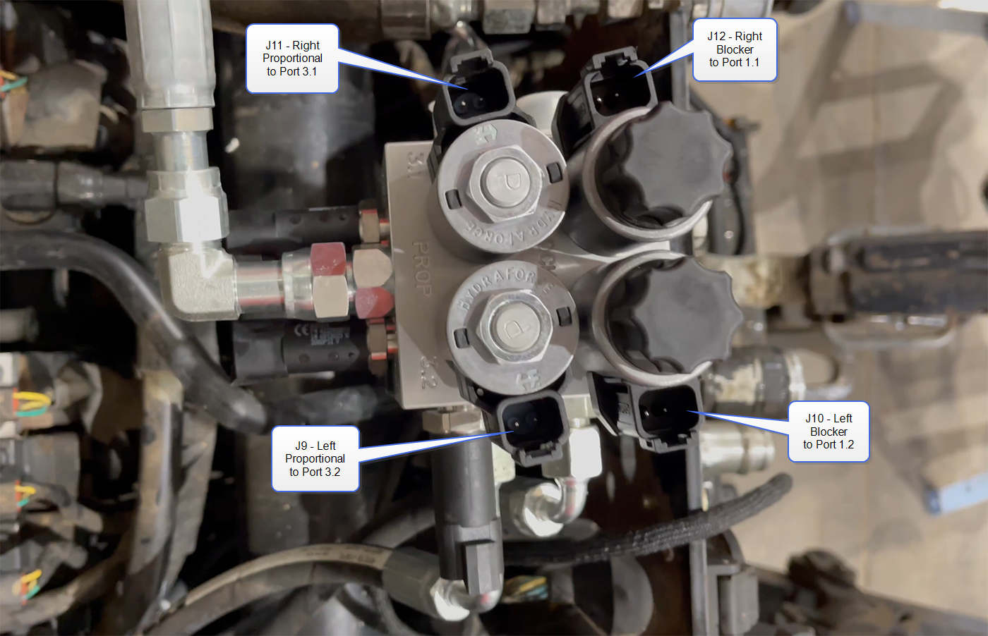
- Connect the 2-pin J9 through J12 connectors to the left and right proportional and blocker valves as shown in the image below.
- Connect the round, 14-pin connector labeled X2M VALVE to the X2F VALVE connector on the main MCM harness (P/N 115-2610-092) at the back of tractor cab.
- Proceed to the Mount and Connect the HDU topic to proceed with the OMNiDRIVE™ installation.
Last Revised:Jul 2024