Mount and Connect the HDU
- 2" hole saw (optional)
Mount the HDU
- Locate the NavController III ECU
 Electronic Control Unit mounted to the rear cab wall.
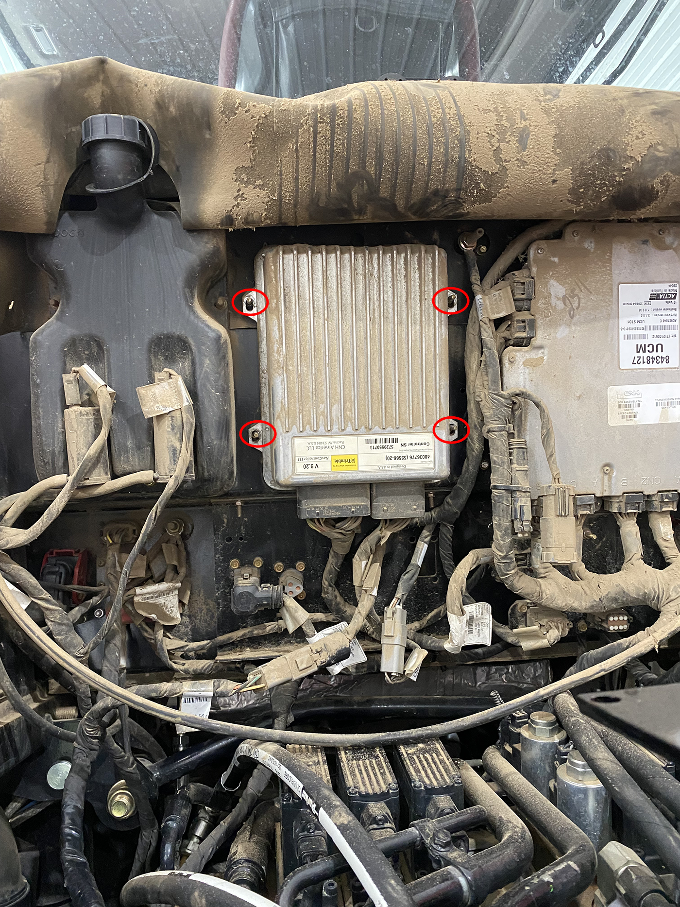
- Remove the nuts securing the ECU and disconnect the large, rectangular connectors from the ECU and remove the ECU from the machine.
Note: The ECU will not be used with the OMNiDRIVE™ system.
- With the NavController III removed, secure the ECU mounting bracket (P/N 107-0172-628) to the mounting studs using the provided M5 flanged locking nuts.
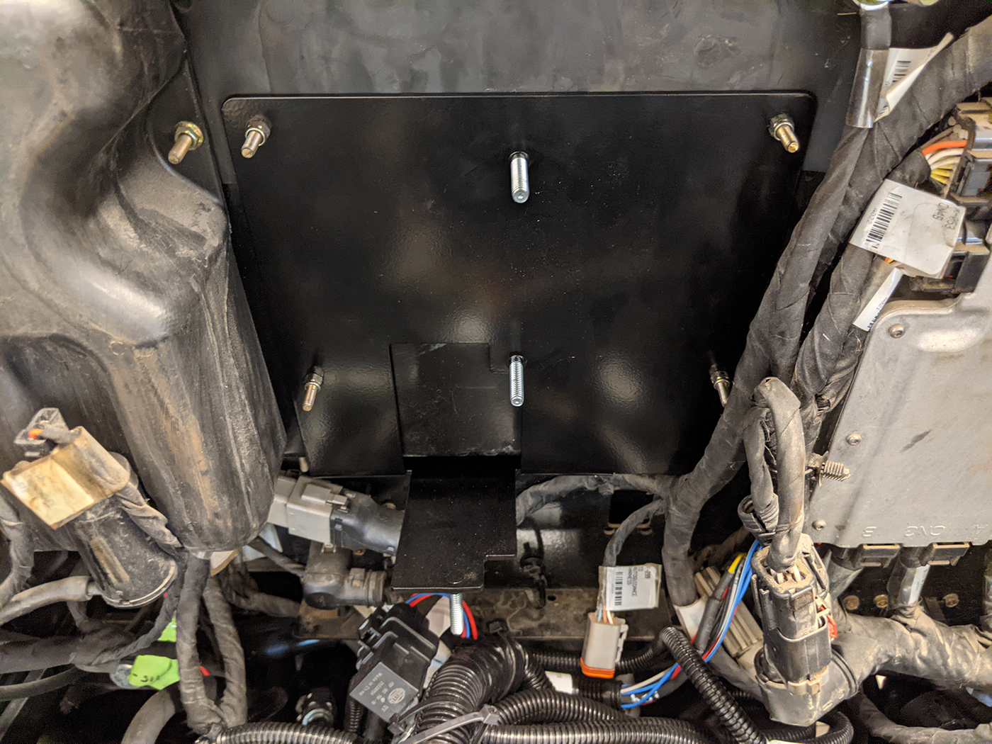
- Place the HDU Hydraulic Drive Unit (P/N 063-0174-194) onto the mounting bracket and secure the ECU with the provided 1/4 in - 20 lock nuts. Mount the HDU with the connectors facing toward the right of the tractor.
Connect the HDU
- Connect the black and gray 12-pin connectors to the HDU mounted at the back of the tractor.
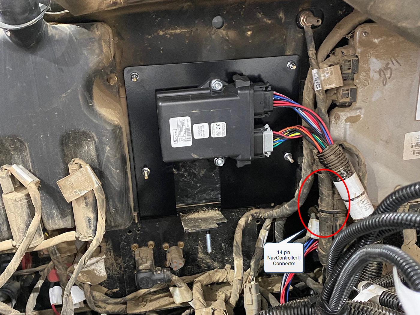
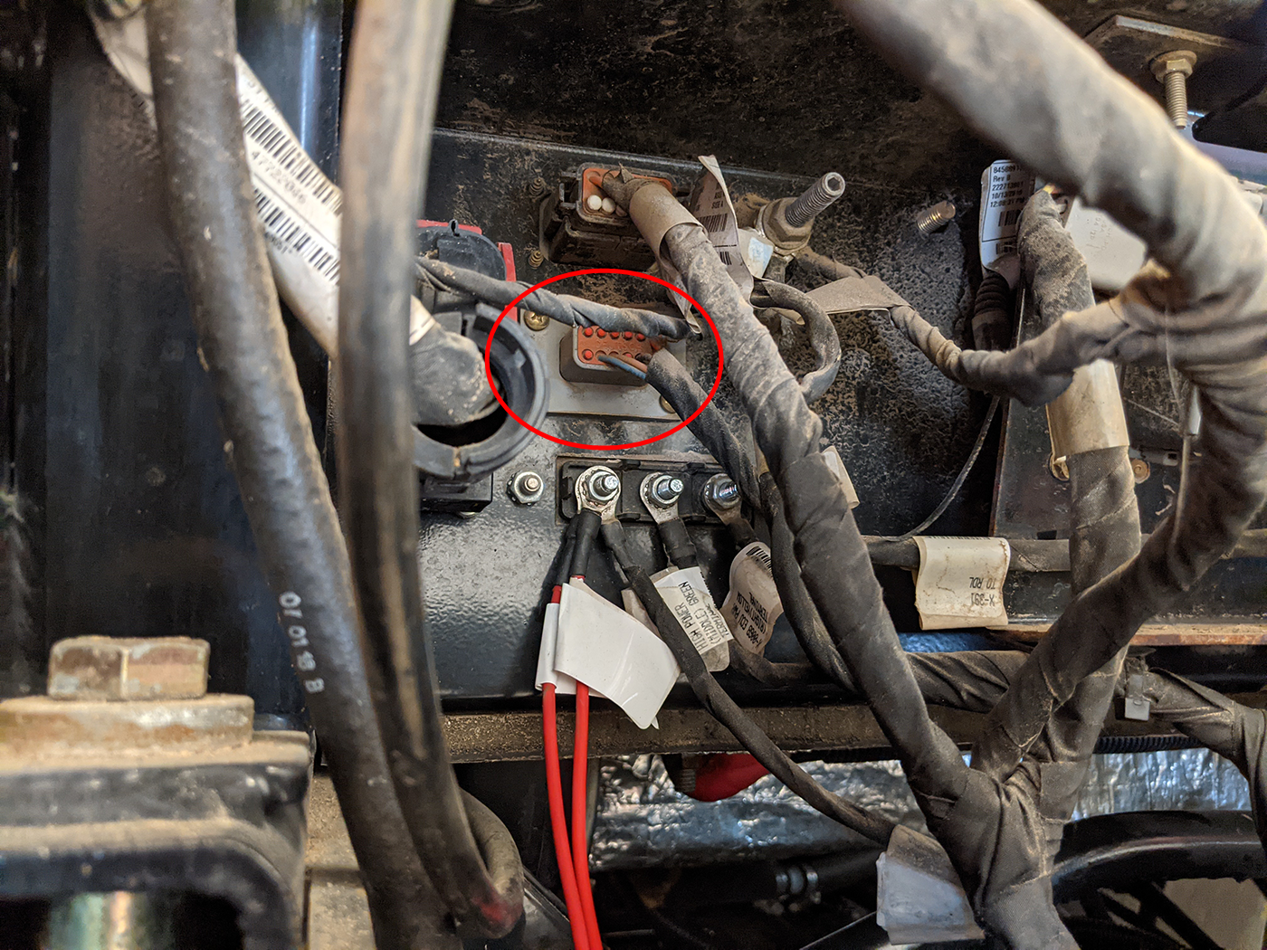
- Trace the NavController III harness to the 14-pin factory connector located to the lower, right of the HDU.
Note: 14-pin connector is tucked behind the lower, left corner of the UCM ECU on the back of the tractor cab.
- Replace the factory bulkhead connector with the 14-pin connector labeled STEERING INPUTS J5 on the HDU power/ground cable (P/N 115-2610-099).
- Trace the factory harness which was disconnected from the NavController III to the 12-pin flange mount connector toward the left of the rear cab.
- Remove the screws securing this connector and insert the 12-pin cavity plug (P/N 408-4001-445) into the open flange mount port.
Note: Remove the NavController III harness from the machine. This harness will not be used with the OMNiDRIVE™ system.
- Locate and disconnect the 4-pin ISOBUS connector on the front (tractor facing side) of the IBBC Implement Bus Breakaway Connector. Connects to the IBIC on the towed implement. bulkhead plate.
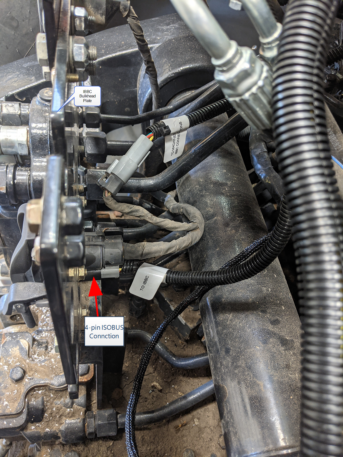
- Tee the connectors labeled ISO CAN TEE into the IBBC bulkhead and the factory 4-pin plug.
- Route and connect the 3-pin connector labeled X8M HDU PWR/GND to the connector labeled X8F HDU PWR on the main MCM harness (P/N 115-2610-092).
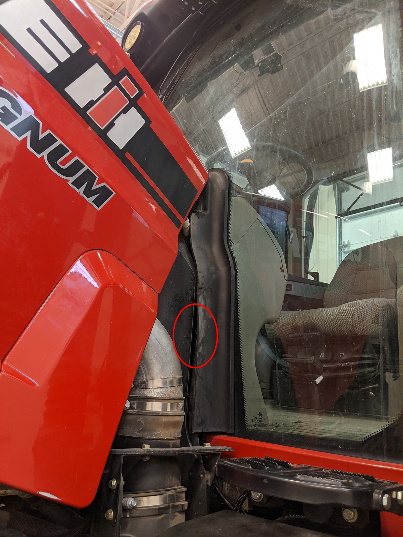
- Route the connector labeled ISOLATION J6 toward the front, left corner of the cab.
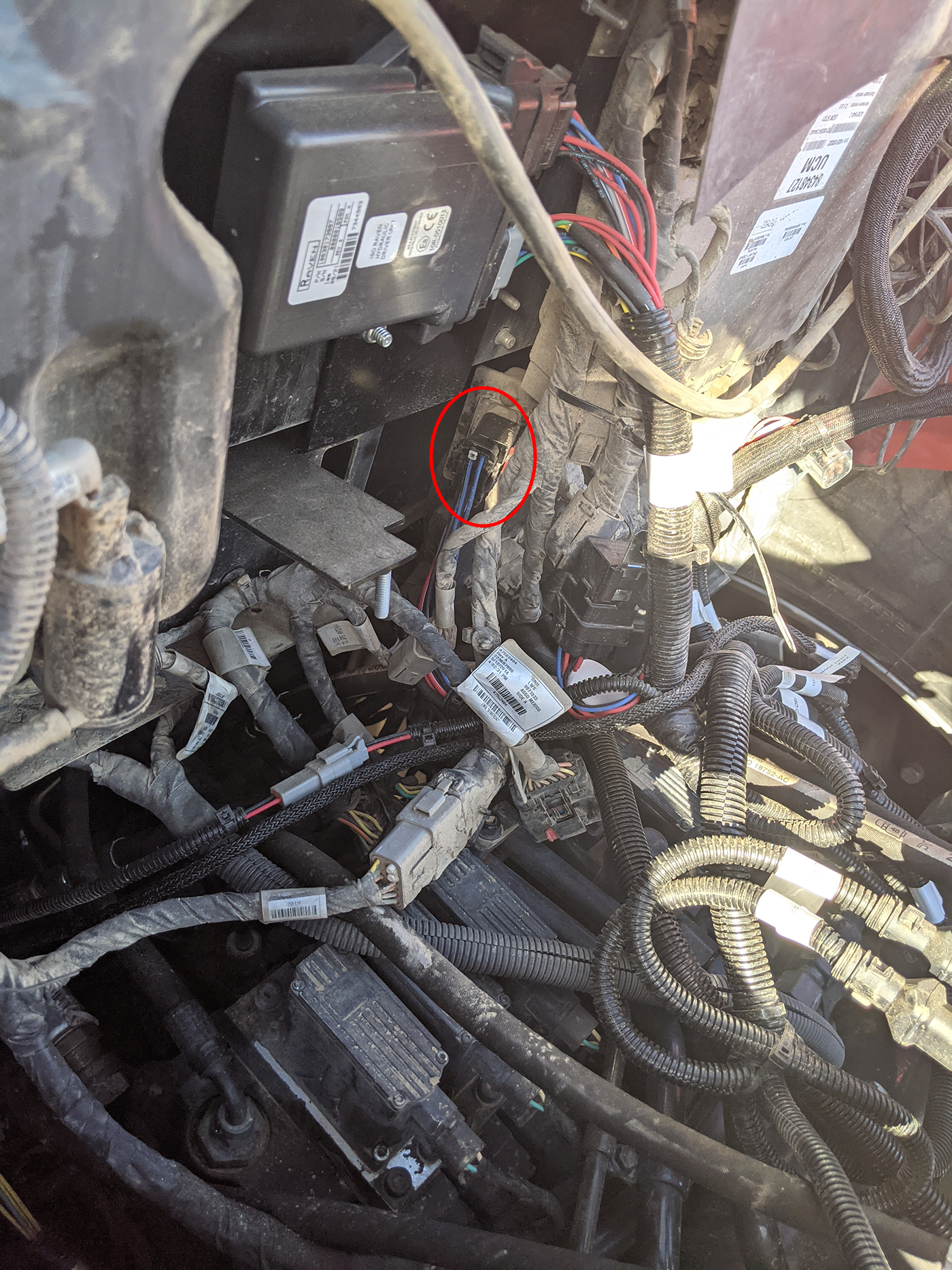
- Open the hood and find the isolation valve located behind the rubber shield toward the top of the engine compartment as shown in the image below.
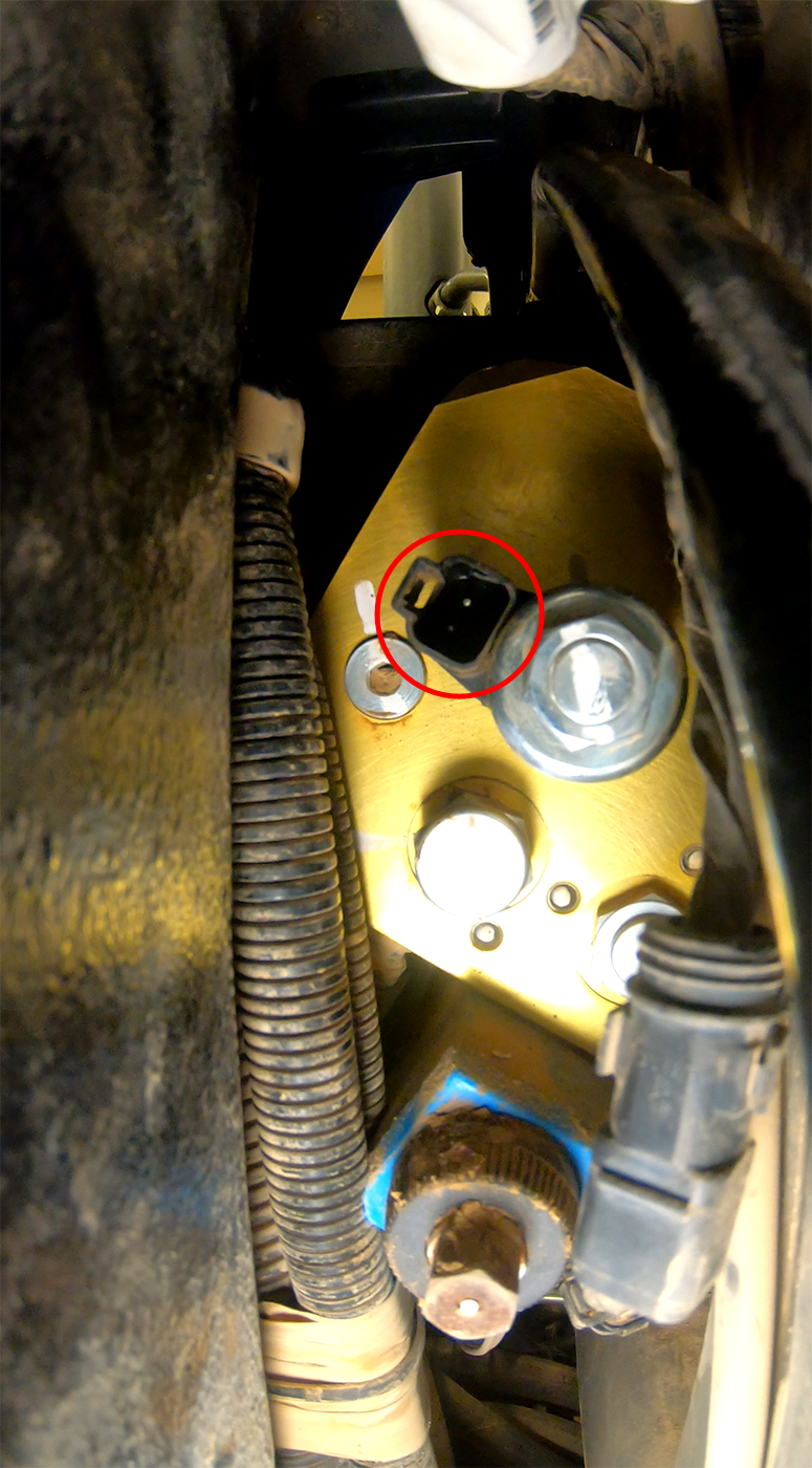
Note: The isolation valve is visible from the right side of the tractor, but is easier to access from the left side.
- Disconnect the factory isolation valve connector and insert the connector labeled ISOLATION J6. Place the cap from the HDU power/ground cable onto the factory isolation valve connector.
- Proceed to the Assemble the Antenna and Camera Brackets topic to continue with the OMNiDRIVE™ tractor installation.
Last Revised: Jul 2024