Install the Bypass Switch and FNRP Breakout Cable
|
|
|
|---|---|
|
|
The implement or machine must remain stationary and switched off with booms or implement sections unfolded and supported during installation or maintenance. |
 warning
- Small flat-head screwdriver
By-Pass Switch and CAN Tee Connections
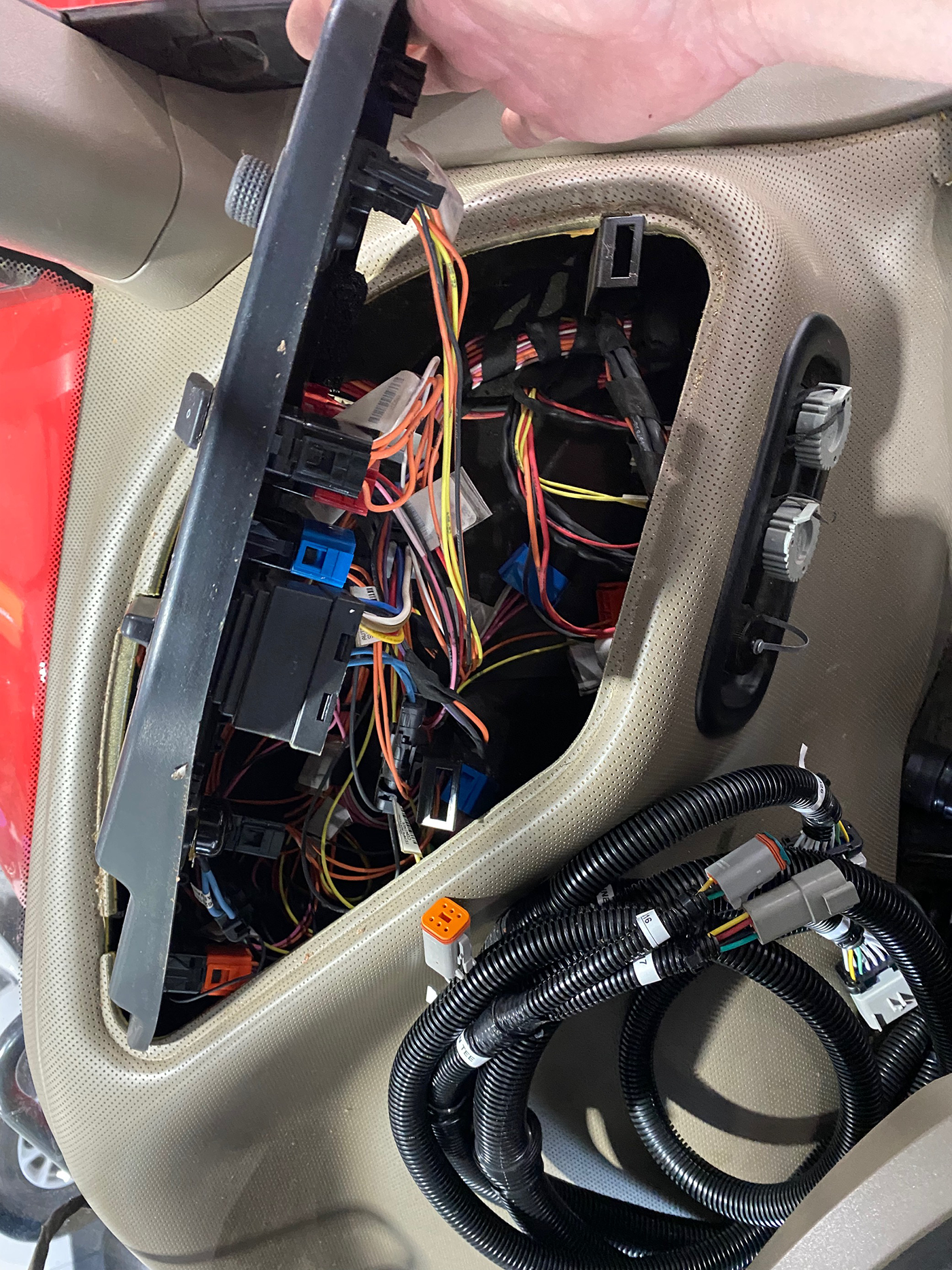
- Locate the machine harness connection labeled (X-280) toward the right side of the fuse panel.
- Disconnect the factory connectors and tee in the connectors labeled MACHINE PRIMARY CAN TEE.
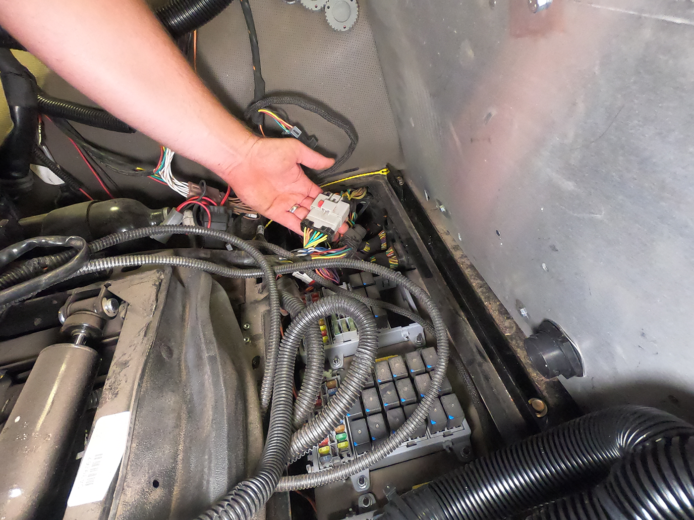
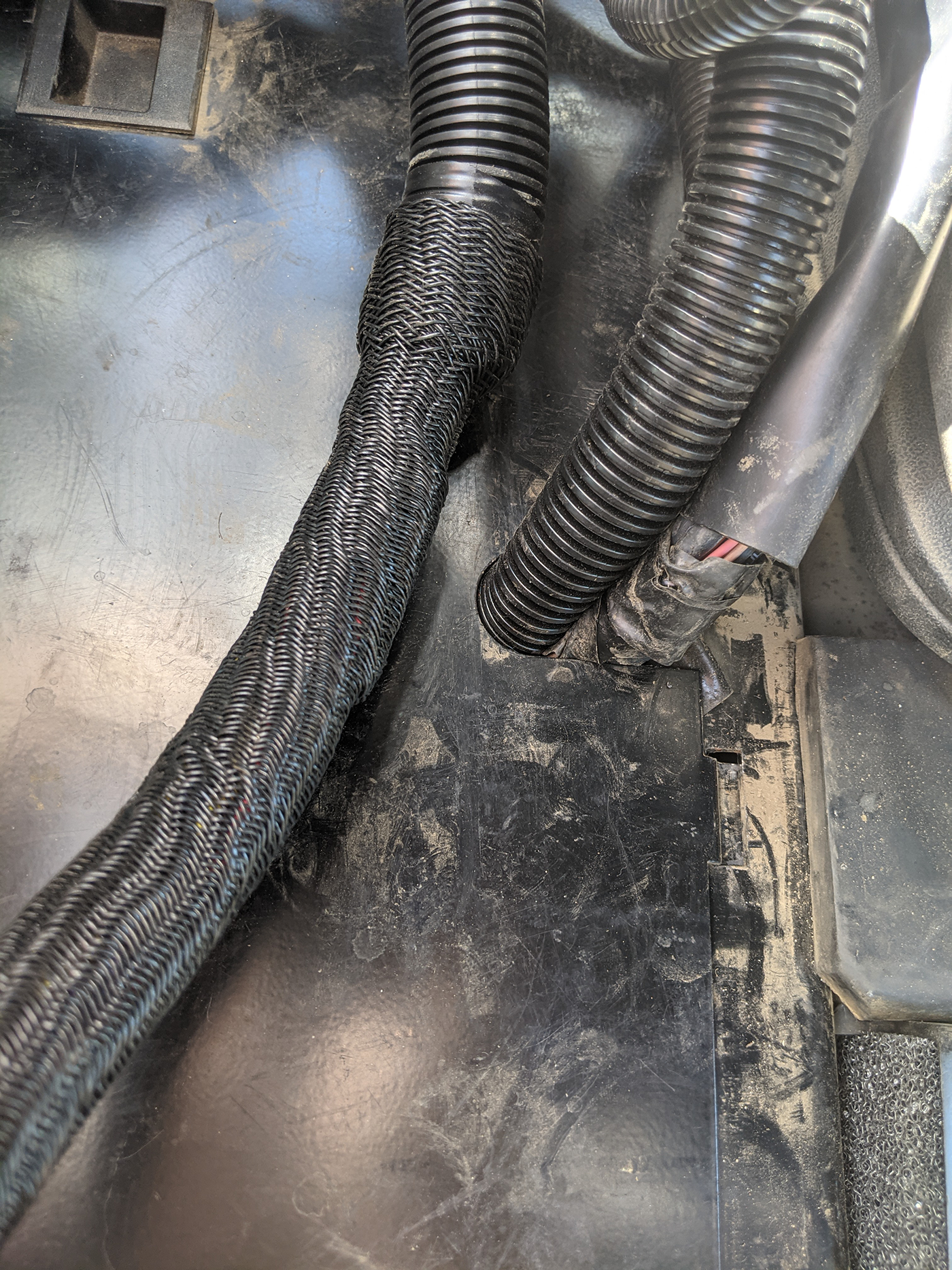
- Locate the floor pass-through from the right, rear corner of the fuse panel into the right console compartment.
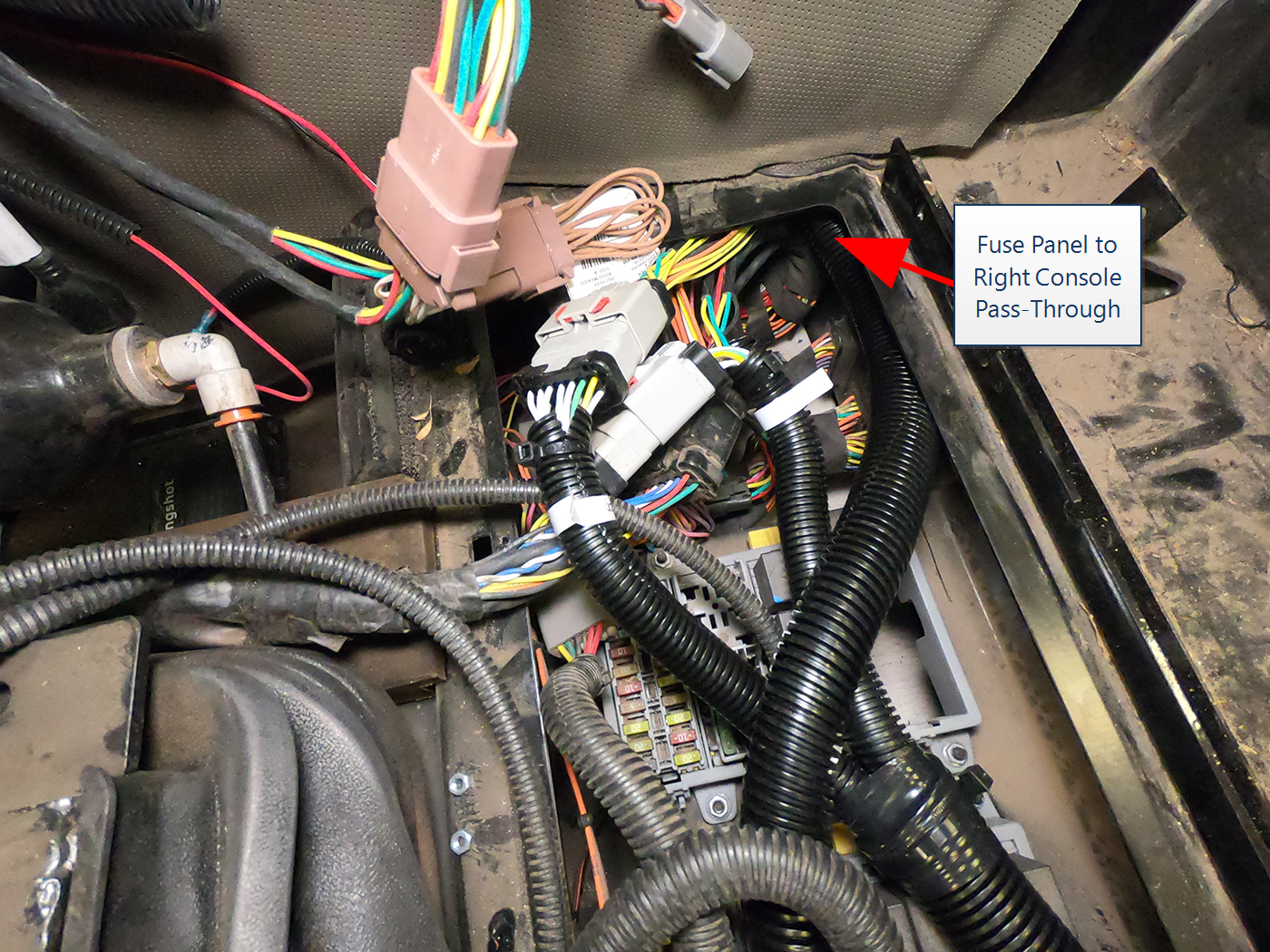
- Feed the branches of the FNRP
 Forward, Neutral, Reverse, Park breakout cable (P/N 115-2610-090) labeled ISO CAN TEE and BYPASS SWITCH J28 through the pass-through into the console at the right, rear corner of the cab.
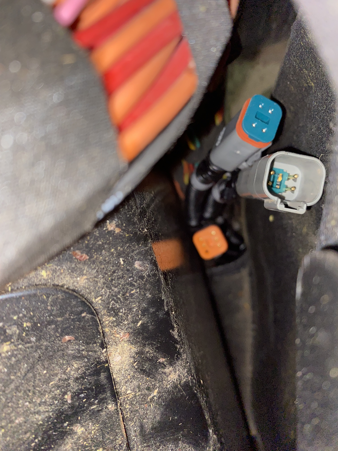
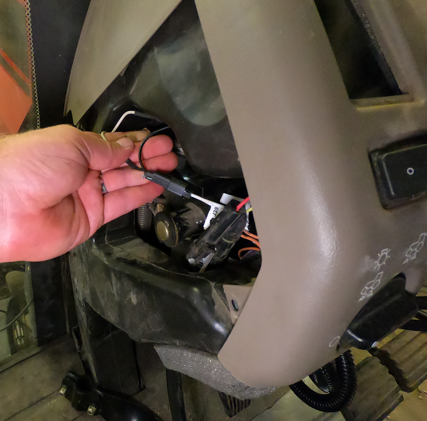
- Locate the factory 4-pin ISOBUS CAN connectors within the right, rear console.
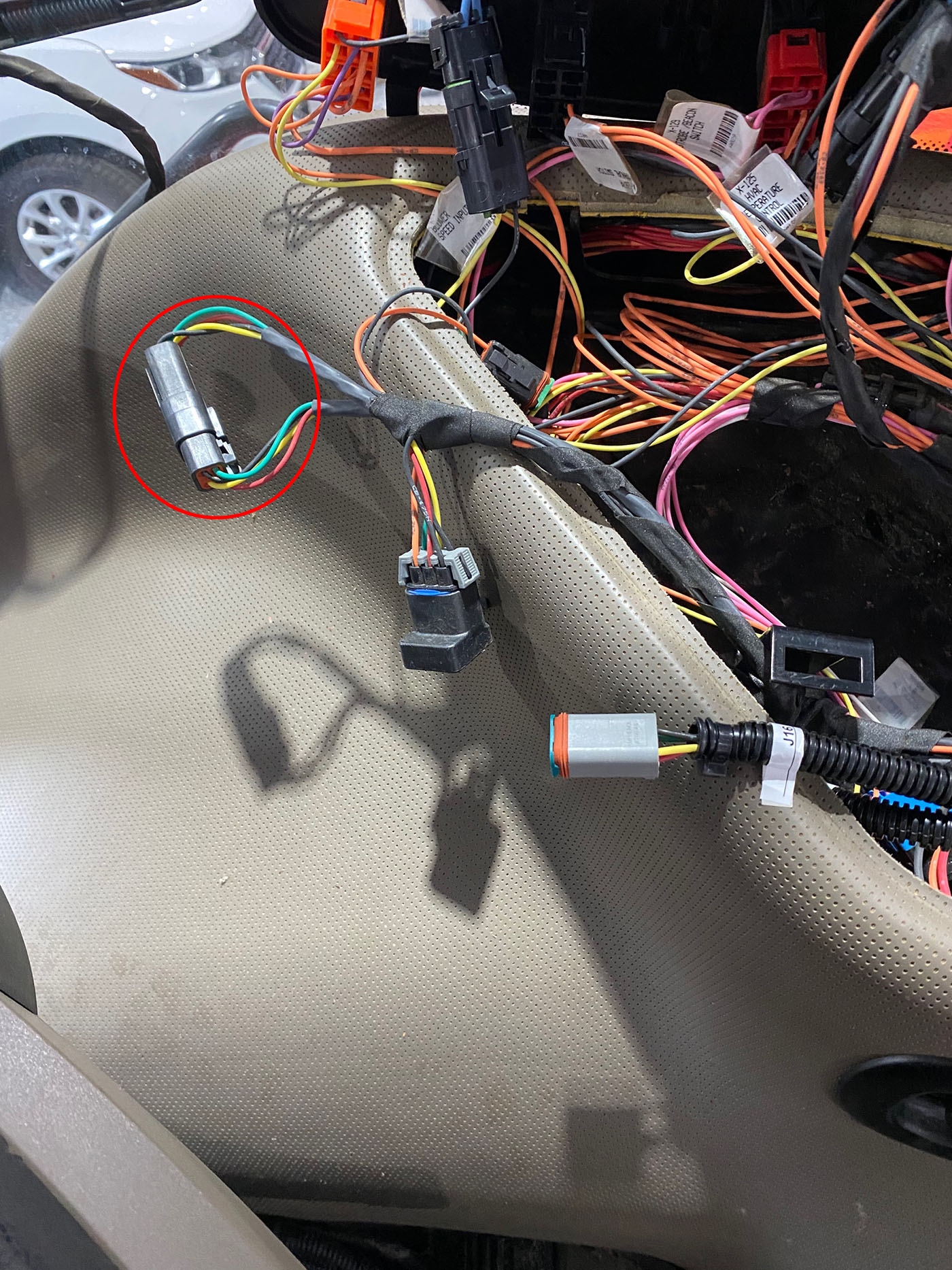
- Disconnect the factory ISO connectors and tee in the connectors labeled ISO CAN TEE from the FNRP breakout cable.
- Select an available slot on the climate control panel and replace the cap with the OMNiDRIVE™ by-pass switch (P/N 412-2011-119).
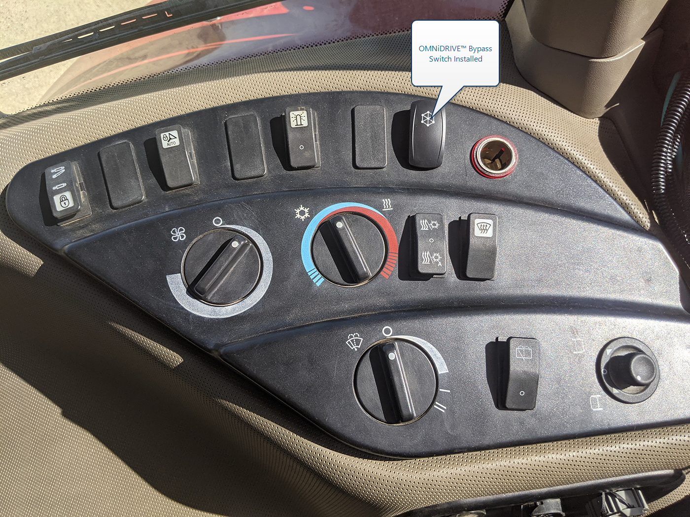
- Insert the connector labeled BYPASS SWITCH to the connector on the by-pass switch.
- Reinstall the climate control panel into the console.
- Replace the fuse panel cover in the cab floor while routing the FNRP breakout cable through the cutout in the cover.
Note: The large, 23-pin connector labeled X5F on the FNRP break out cable will connect to the OMNiDRIVE™ device plate as described in Mount the Field Hub and OMNiDRIVE™ Device Plate.
Clutch, Brake, and Bypass Switch Connections
|
|
|
|---|---|
|
|
Route cables to avoid creating a tripping hazard and away from possible damage due to pinch points, heat generating and moving components, etc. |

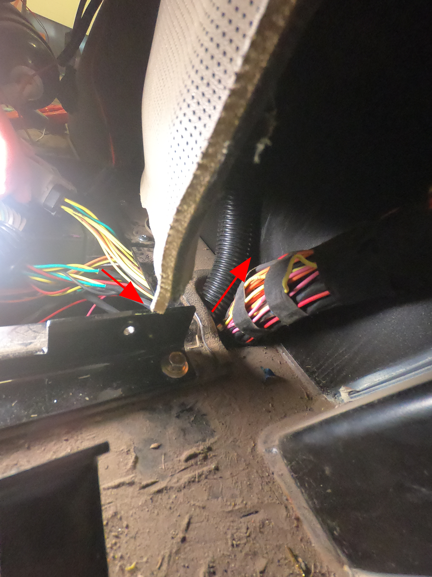
- Route the LEFT and RIGHT BRAKE SWITCH, BOTTOM OF CLUTCH, and FNRP RELAY connectors on the FNRP breakout cable (P/N 115-2610-090) along the right side of the cab, to the right side of the steering column and inside the steering column structure.
- Locate the factory FNRP connector at the front, center of the steering column near the top of the foot pedals.

- Route the connectors on the FNRP breakout cable (P/N 115-2610-090) labeled FNRP RELAY through the steering column to the factory connector and tee into the factory FNRP connection.
- On the left side of the steering column, locate the factory connectors labeled BOTTOM OF CLUTCH.
- Route the connectors labeled BOTTOM OF CLUTCH through the steering column and tee into the factory clutch connection.
Note: A small flat-head screwdriver may make it easier to disconnect the factory connectors.
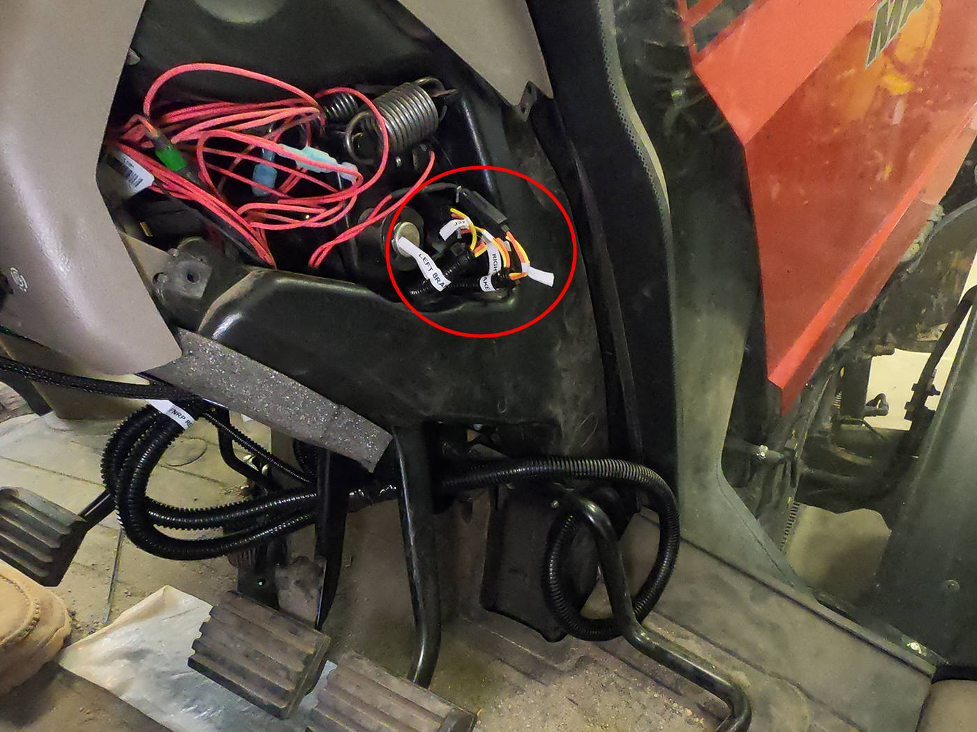
- On the right side of the steering column, locate the factory connectors labeled LEFT TOP OF BRAKE and RIGHT TOP OF BRAKE.
Note: It may be easier to access the brake connectors with the steering column vent assembly removed.
- Route the RIGHT BRAKE SWITCH and LEFT BRAKE SWITCH connectors on the FNRP breakout cable through the steering column and tee into the right and left brake connections, respectively.
Note: Be sure to match the left and right brake switch connectors and wire colors on the FNRP breakout cable tees with the factory brake switch connectors. The left and right switches are denoted when facing the forward travel direction of the machine.
- Coil and secure any excess cable length behind the operator seat and secure the FNRP cable to avoid any interference with the brake or throttle pedals and to avoid tripping hazards. Review the Recommendations and Best Practices topic for additional information regarding cable routing.
- Proceed to the Mount the Field Hub and OMNiDRIVE™ Device Plate topic to continue the OMNiDRIVE™ installation.
Last Revised:Jul 2024