Mount the Field Hub and OMNiDRIVE™ Device Plate
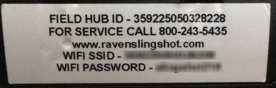
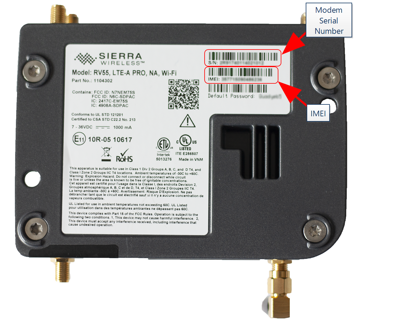
Note: During the installation process, note the serial number and bar code of the following devices and the machine on which each device is installed:
- Slingshot®Field Hub
- RS Lite
This information will be required during device registration and field provisioning procedures and will help locate each device within the Slingshot® portal.
Note: Please allow up to 4 business days to activate the Field Hub. Once activation has been completed, a confirmation email will be sent to the customer and an OTA![]() (Over the Air) Software updates and other information pushed from Slingshot® servers via the Slingshot® system. software update will be pushed to the Field Hub the next time the device powers up. It may be recommended to complete and submit the OLAF
(Over the Air) Software updates and other information pushed from Slingshot® servers via the Slingshot® system. software update will be pushed to the Field Hub the next time the device powers up. It may be recommended to complete and submit the OLAF![]() Online Activation Form procedures for the Field Hub on all OMNiDRIVE™ machines. Refer to the following for additional assistance:
Online Activation Form procedures for the Field Hub on all OMNiDRIVE™ machines. Refer to the following for additional assistance:
Note: These manuals are available at https://portal.ravenprecision.com or by using the links above. Please refer to these documents when installing the OMNiDRIVE™ system.
|
notice |
|
|---|---|
|
|
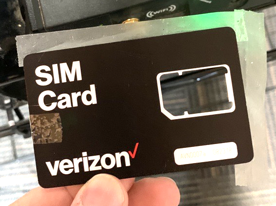
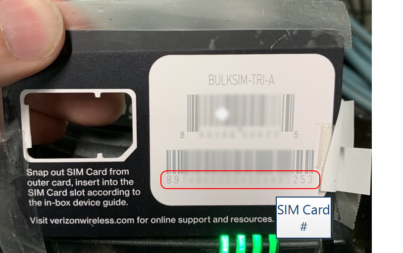
The information affixed to the bottom of the Field Hub will be required to activate the device and provision the OMNiDRIVE™ system. Before mounting the Field Hub, it is strongly recommended to remove the SIM |

- Using the provided hardware and predrilled holes, mount the Slingshot® Field Hub (P/N 063-0174-146B) on top of the OMNiDRIVE™ device plate (P/N 063-2610-031).
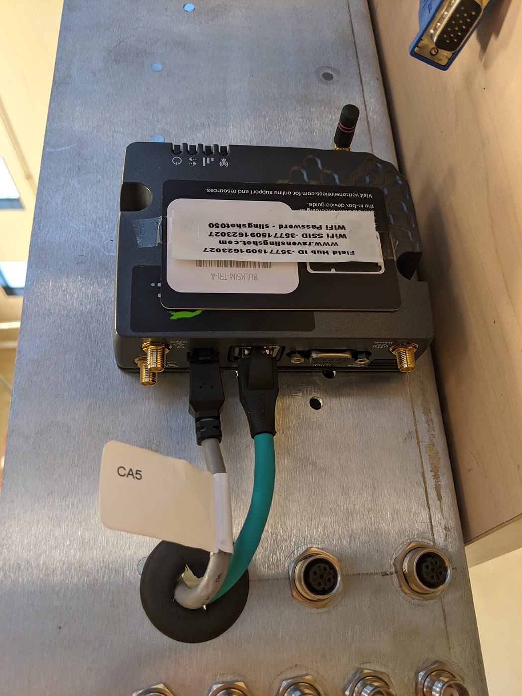
Note: Mount the Field Hub with the power and Ethernet ports facing toward the right side of the cab (toward the camera connections and grommet on the device plate).
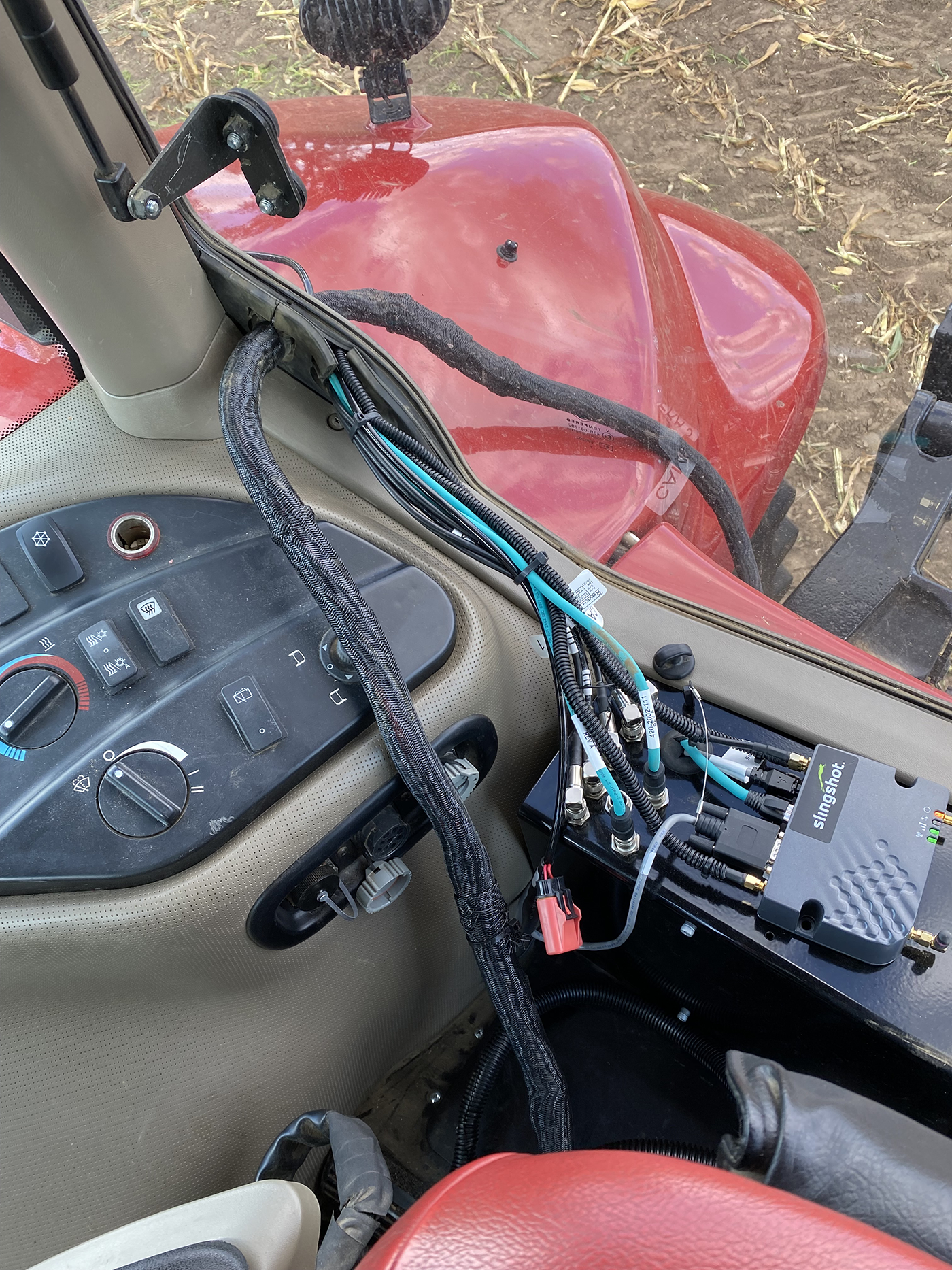
- Locate the 4-pin connector labeled MODEM on the MCM device plate cable (P/N 115-2610-098) already connected to the Ethernet switch.
- Route the 4-pin MODEM connector through the grommet in the top of the device plate and connect it to the 4-pin power port on the Slingshot® Field Hub.
Note: Use care when feeding cables through the grommet to avoid bending or breaking the connectors.
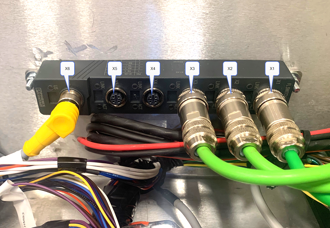
- Connect the 4-pin Ethernet cable (P/N 420-2002-114) to the X5 port on the Ethernet switch.
- Route the Ethernet cable through the grommet in the top of the device plate and connect it to the Ethernet port on the Field Hub.
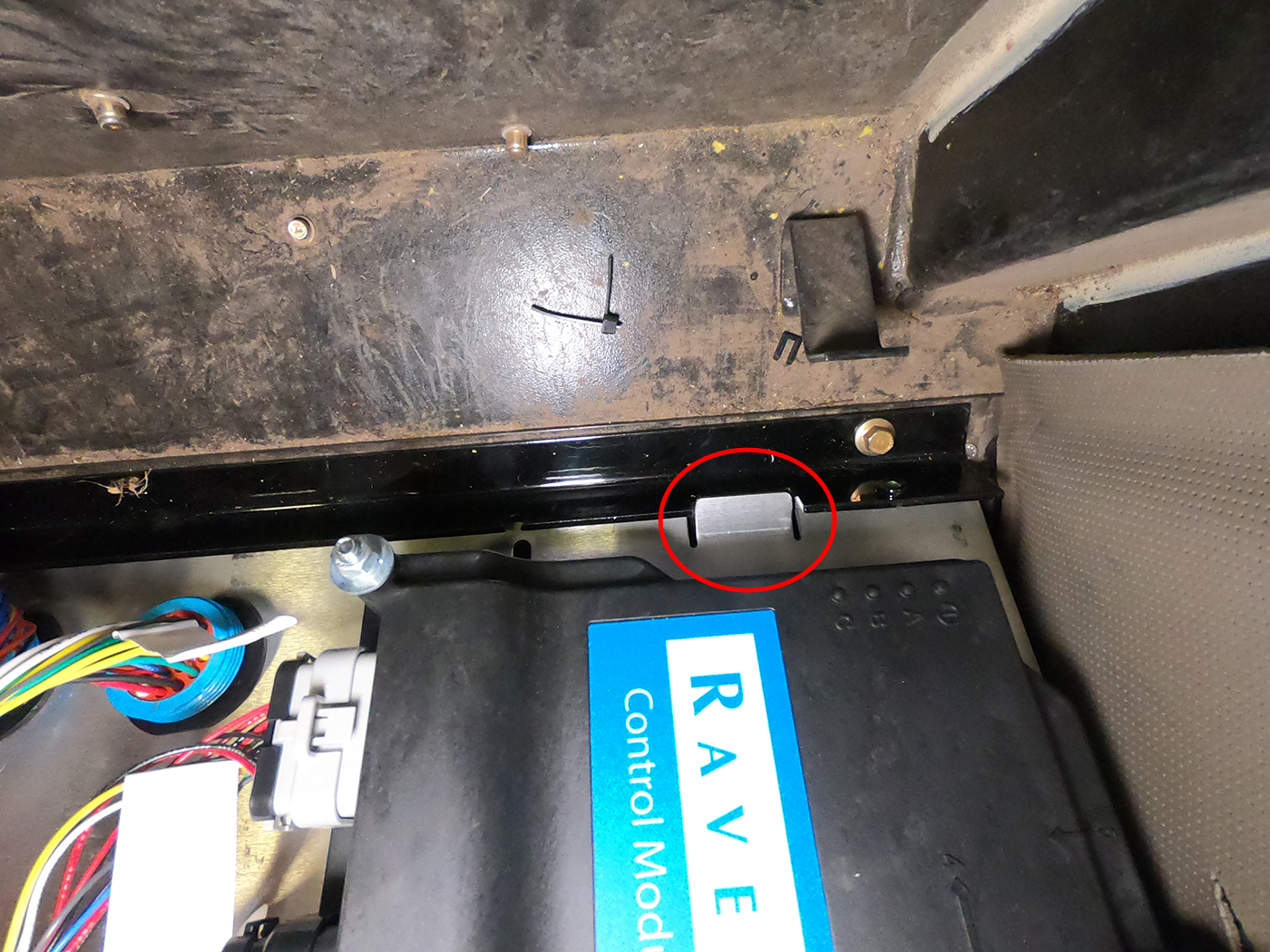
- Install device plate floor channel (P/N 107-2610-040) using the factory hardware in the location shown below.
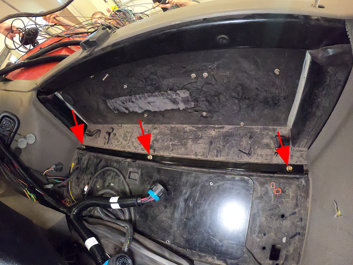
Note: Mount the floor channel with the raised face of the channel toward the front of the cab.
- Lower the device plate behind the operator seat and set the device plate into the floor channel. Ensure the tabs on the device plate interface with the floor channel.
Note: Two wing nuts and two hex-head screws will need to be removed to allow device plate to be installed. Replace the wing nut and hex-head screws after the device plate is installed. It is not recommended to secure the device plate until the main MCM harness and the machine connections are made in the fuse panel under the floor of the cab in this area.
- Connect the large, 23-pin connector labeled X5F on the FNRP
 Forward, Neutral, Reverse, Park break out cable to the far left bulkhead connector on the device place.
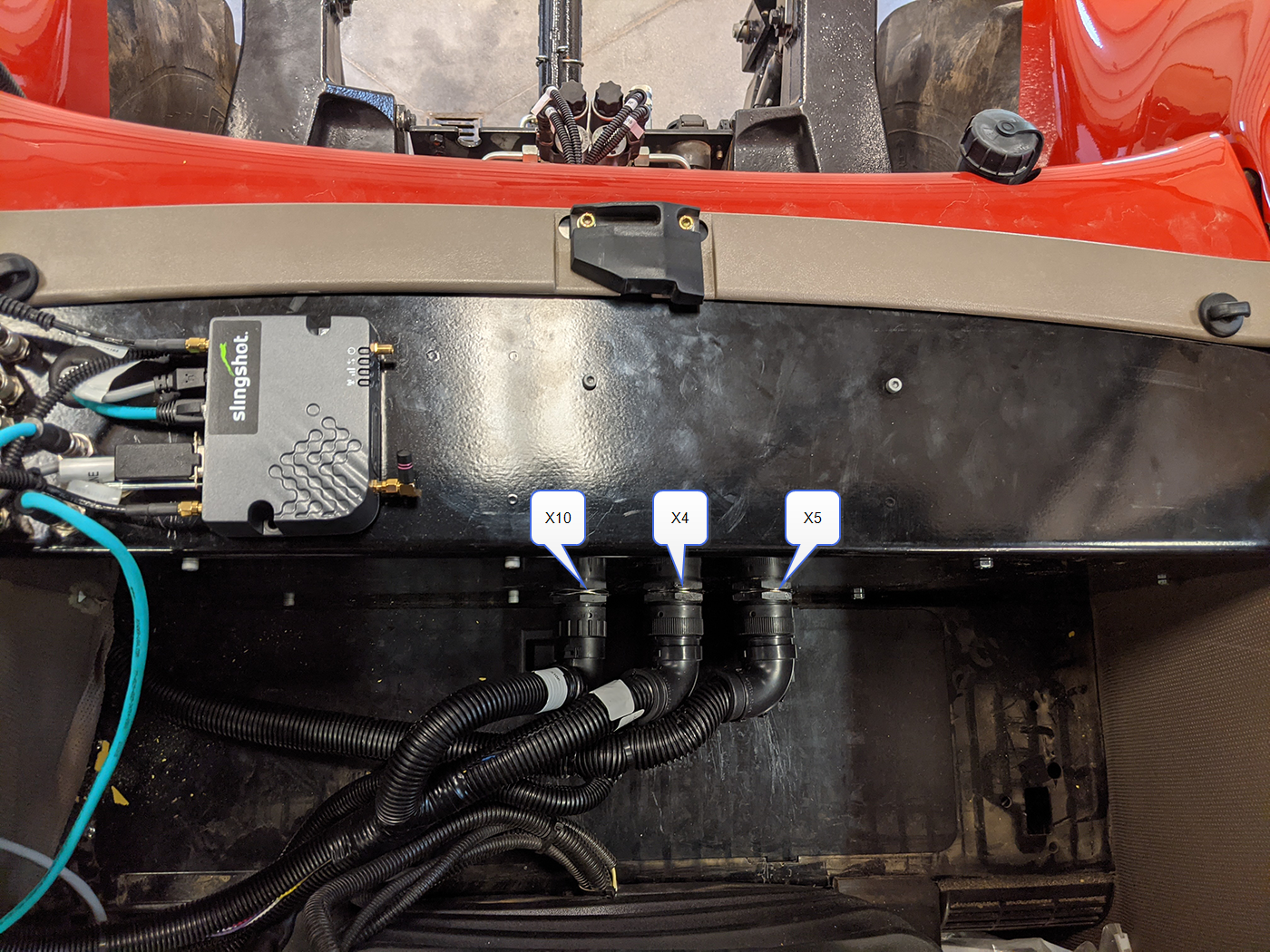
- On the main MCM harness (P/N 115-2610-092), locate and connect the two round connectors labeled X4F and X10F to the center (X4M) and left (X10M) bulkhead ports on the device plate.
- Route the main MCM harness through the grommet in the lower, right corner of the rear cab window.
Note: The connectors labeled X3F and X6F LIGHTS will route up the right, rear post to the cab roof. The remaining connectors on the main MCM harness will connect with other OMNiDRIVE™ components at the rear of the tractor cab.
- Proceed to the Mount and Connect the Lockout Switch topic to continue with the installation process on the tractor.
Last Revised: Jul 2024