Mount and Connect the Radar Assembly (Case IH Magnum)
- Metric socket set - 5 to 24 mm
- Metric Allen wrenches - up to 8 mm
- Tape measure
- Digital level (e.g. mobile phone with level app)
Mount the Radar Sensor
Note: A weight rack is required for mounting the radar sensor. Mounting the radar to a rock box is not supported.
- Insert the radar weight mount bracket (P/N 116-0159-866) in between the weights. Be sure the vertical post is centered between the headlights.
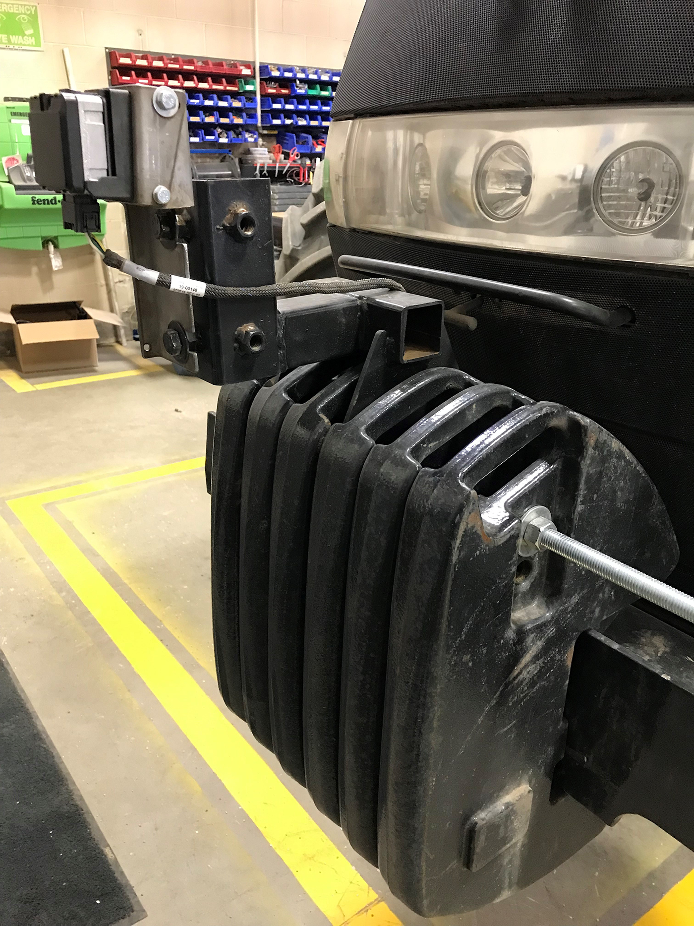
Note: Shift the weights if necessary to properly center the radar bracket.
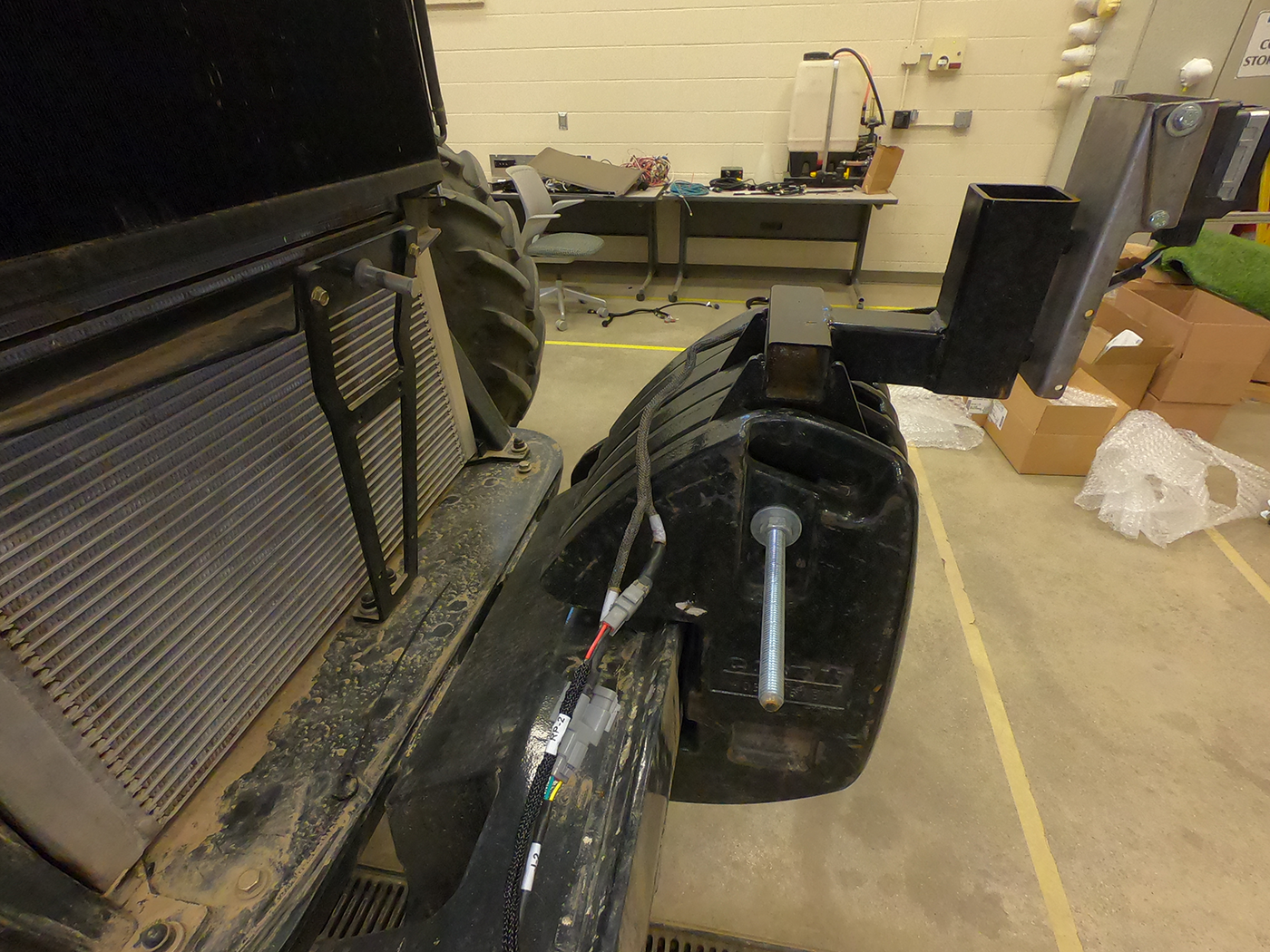
- Insert the 5/8 in. threaded rod (P/N 311-8000-009) through the top hole in the weights and the top hole of the bracket tabs.
- Secure the radar weight mount bracket using a 5/8 in. flat washer, split-lock washer, and nut on each side of the weights and tighten.
Note: Cut off any excess rod length not needed for your application as desired. If the tractor weight configuration could change, it may be desirable to leave extra length available to secure weights as needed.
- Attach the radar weight bracket (P/N 107-2610-053) to the forward facing threaded post holes. Use the provided 1/2" bolts, split lock washers, and flat washers.
- Mount the radar (P/N 063-0174-105) to the radar adjustment plate (P/N 107-2610-051) using the provided M6 screws and washers.
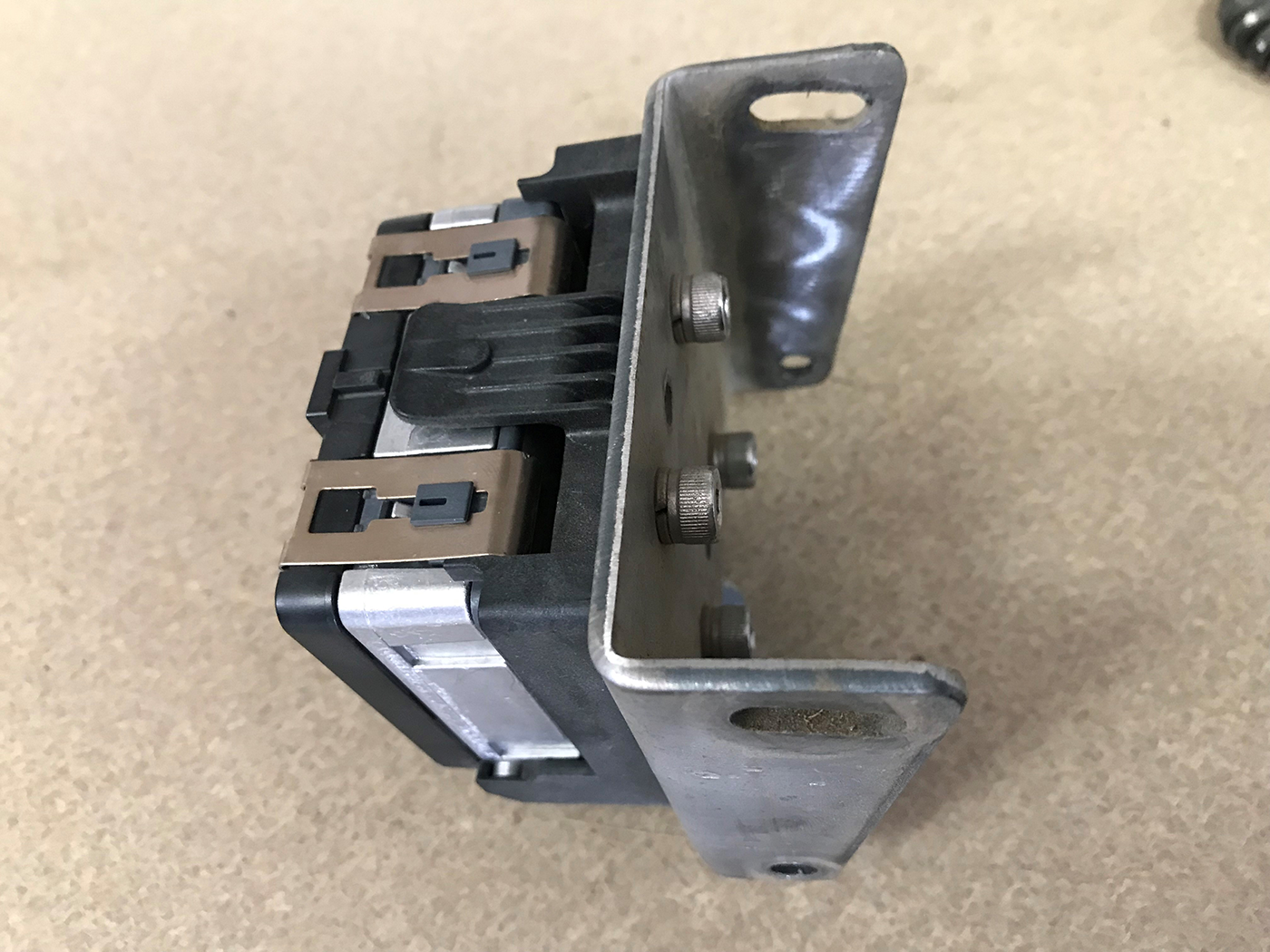
- Secure the adjustment plate to the radar weight mount using for M6 bolts and lock washers.
Calibrate the Radar Sensor
- Locate the ground speed radar and bracket underneath the tractor near the center of the cab. This is a known level surface of the tractor for correct ground speed readings.
- Measure angle of ground speed radar bracket by placing a digital level or cell phone with level app along the edge of the bracket.
- Zero the level to this surface.
- Place the level on the front of the radar assembly.
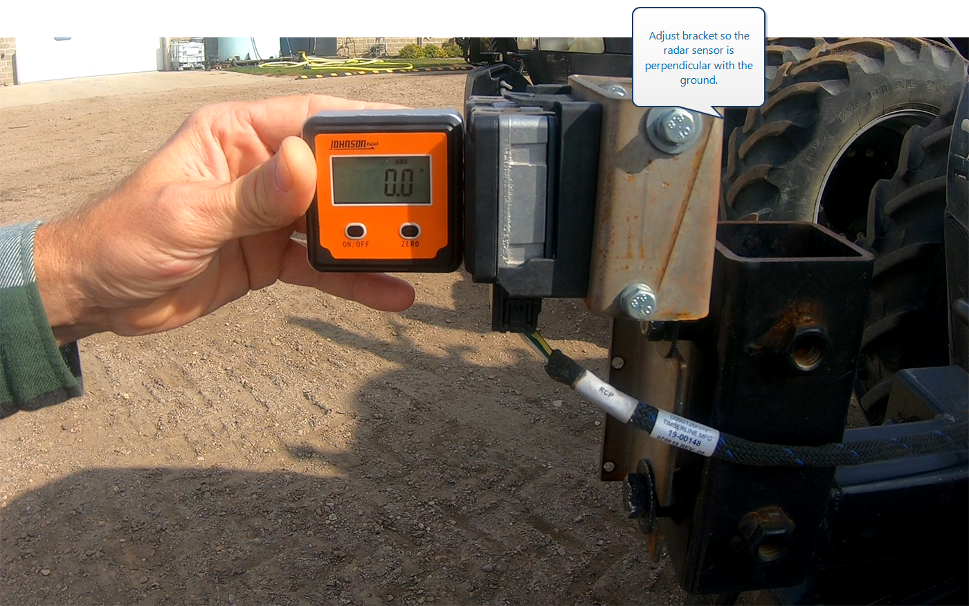
- Loosen the radar bracket.
- Use the level to measure and adjust the angle of the radar assembly to 0° (±0.5°) or perpendicular with the ground and the ground speed radar bracket measurement.
- Tighten the bracket and recheck the level measurement.
Connect the Radar Harness
-
- Connect the radar pigtail cable (P/N 115-2610-019) to the radar assembly.
-
Note: Two 3-pin, Y-adapters (P/N 408-4002-811) are connected to the radar cable and a 3-pin terminator (P/N 408-4002-734) has already been installed in each adapter.
-
Note:
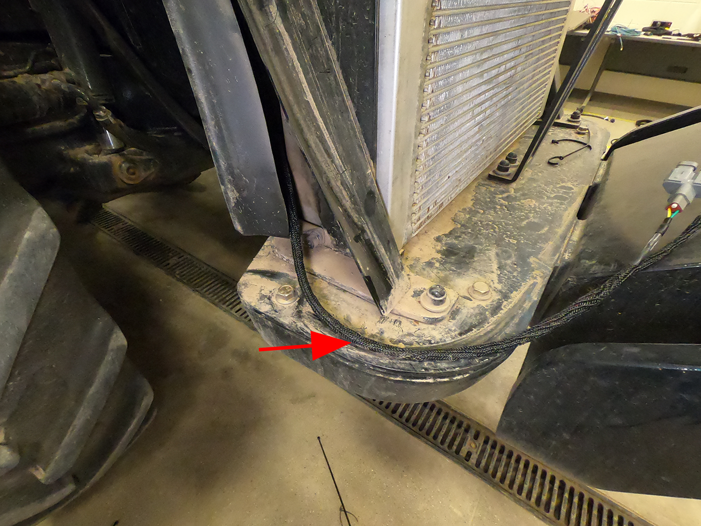
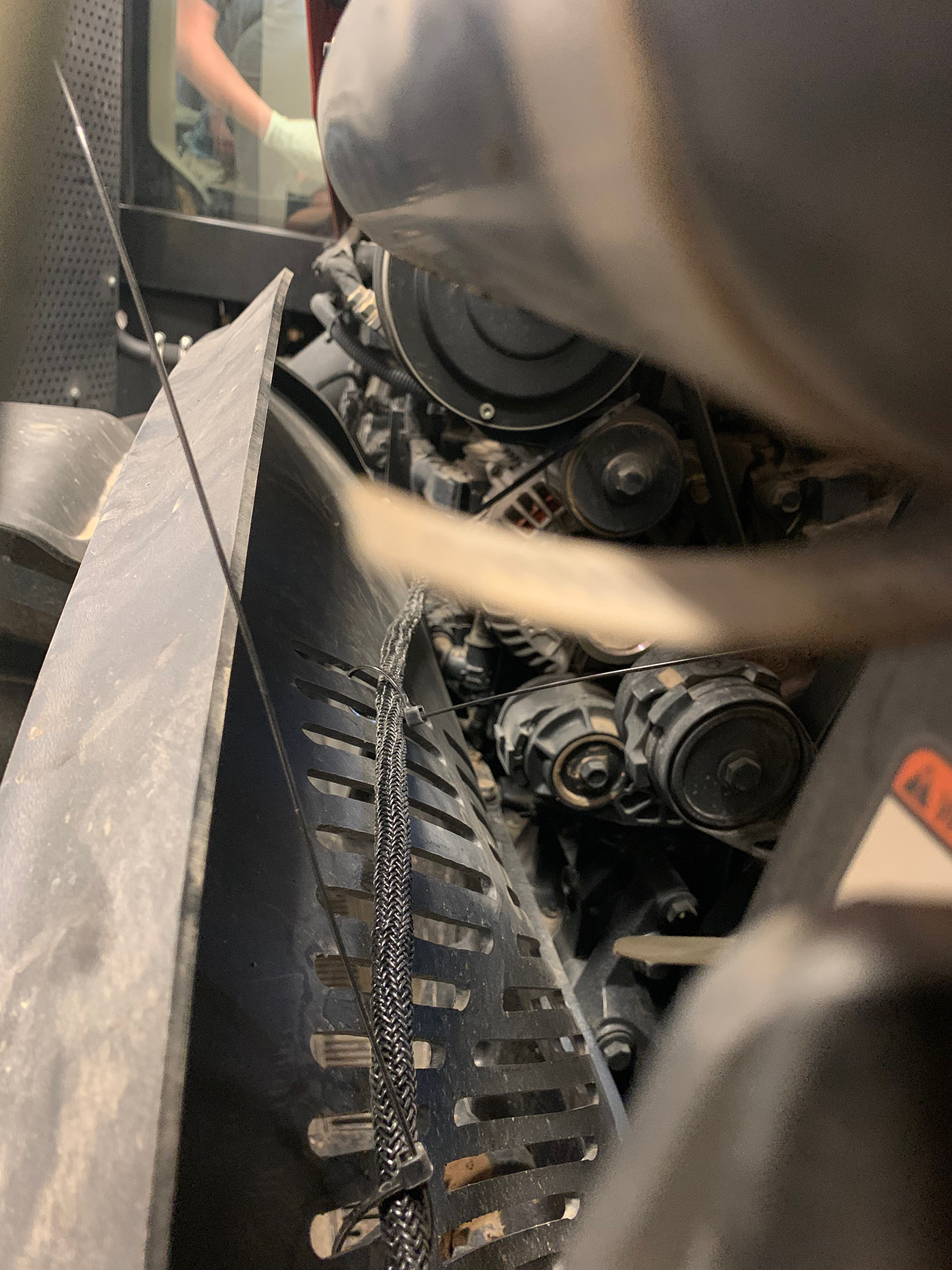
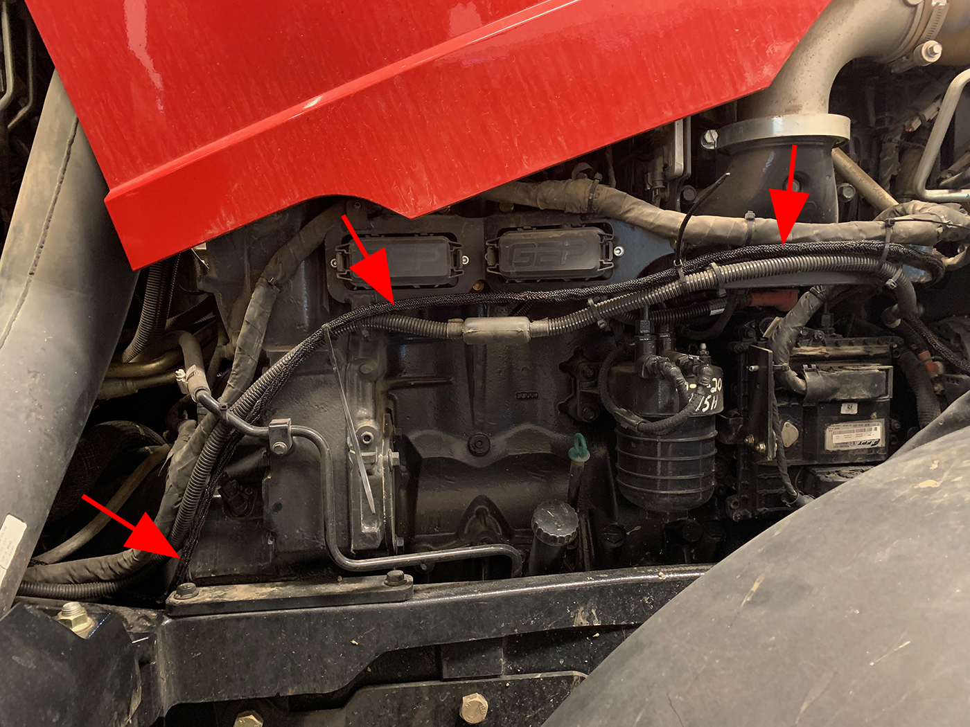
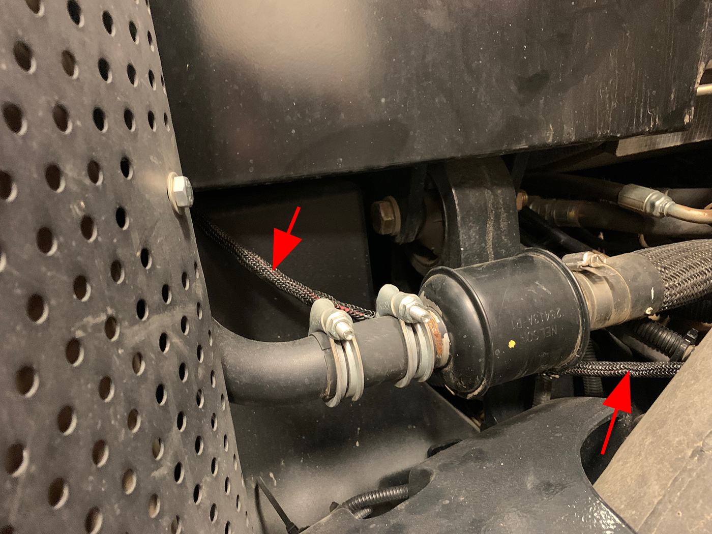
- Secure the cable with the provided zip ties.
- Connect the radar harness to the connector labeled X12F RADAR on the main MCM cable (P/N 115-2610-092).
-
Last Revised: Jul 2024