Mount and Connect the Radar Assembly (New Holland T8)
- Metric socket set - 5 to 24 mm
- Metric Allen wrenches - up to 8 mm
- Tape measure
- Digital level (e.g. mobile phone with level app)
Mount the Radar Sensor
Note: A weight rack is required for mounting the radar sensor. Mounting the radar to a rock box is not supported.
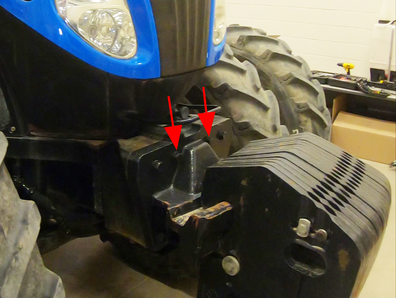
- Remove the weights from the weight bracket.
- Remove the two bolts from the weight bracket.
- Install the radar weight mount base (P/N 107-2610-061) with the previously removed bolts. Torque the weight bracket bolts to 610 - 730 Nm [450 - 540 lb-ft].
notice

Review and reference the manufacturer's recommended service and maintenance procedures while working on the machine or equipment. Contact your local equipment dealer or service provider for additional information with OEM documentation or for assistance with specific procedures.
- Reinstall the weights.
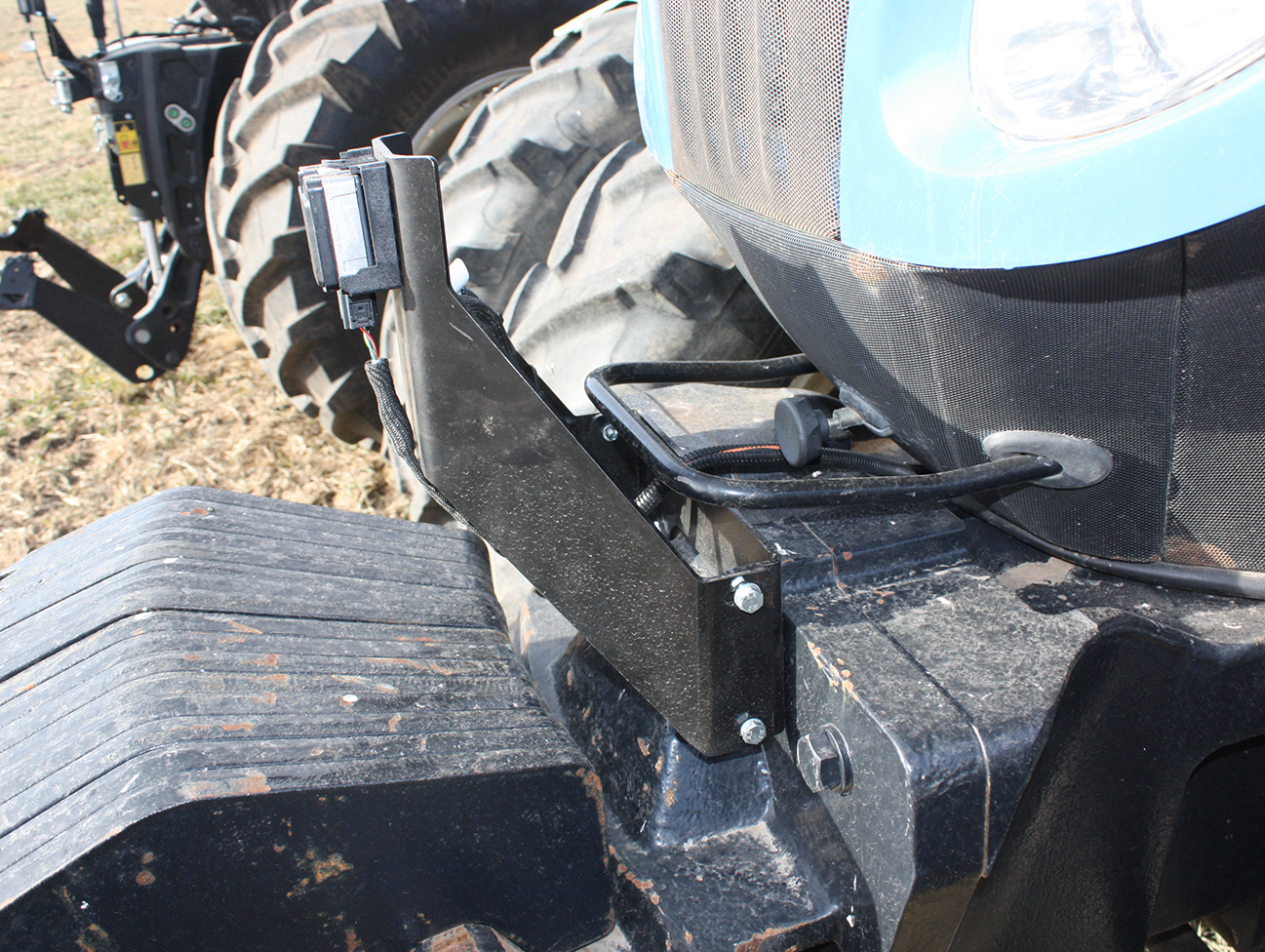
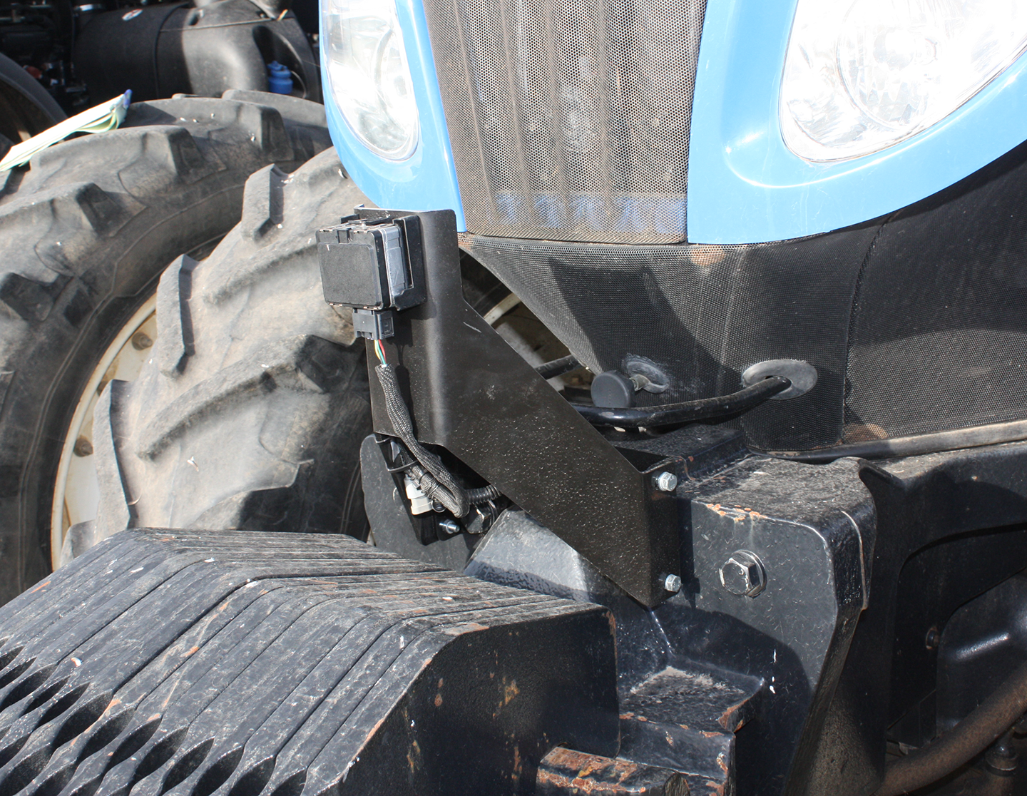
- Install the radar bracket (P/N 107-2610-062) to the radar mount base with the provided M8 hardware.
- Mount the radar (P/N 063-0174-105) to the radar bracket using the provided M6 screws and washers.
Calibrate the Radar Sensor
- Locate the ground speed radar and bracket underneath the tractor near the center of the cab. This is a known level surface of the tractor for correct ground speed readings.
- Measure angle of ground speed radar bracket by placing a digital level or cell phone with level app along the edge of the bracket.
- Zero the level to this surface.
- Place the level on the front of the radar assembly.
- Loosen the radar bracket.
- Use the level to measure and adjust the angle of the radar assembly to 0° (±0.5°) or perpendicular with the ground and the ground speed radar bracket measurement.
- Tighten the bracket and recheck the level measurement.
Note: Recheck the radar angle whenever ballast weights are added or removed.
Connect the Radar Harness
-
- Connect the radar pigtail cable (P/N 115-2610-019) to the radar assembly.
-
Note: Two 3-pin, Y-adapters (P/N 408-4002-811) are connected to the radar cable and a 3-pin terminator (P/N 408-4002-734) has already been installed in each adapter.
-
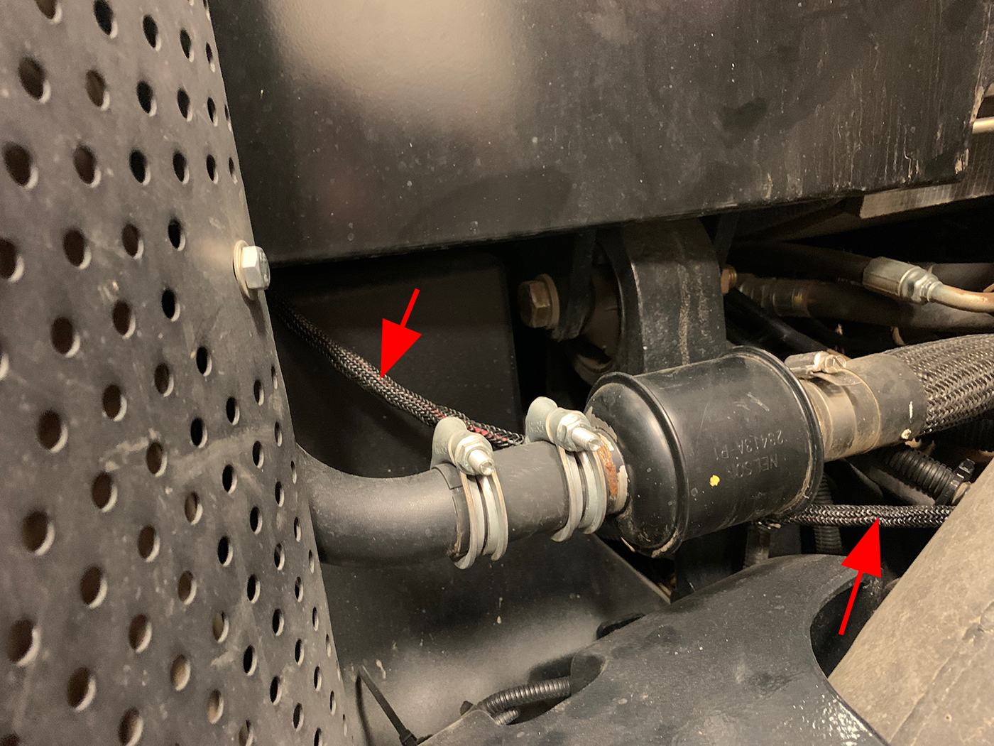
Note: Avoid components which generate excessive heat and hot hydraulic lines. Review Recommendations and Best Practices for additional information on routing and securing cables and harnesses.
- Secure the cable with the provided zip ties.
- Connect the radar harness to the connector labeled X12F RADAR on the main MCM cable (P/N 115-2610-092).
-
Last Revised:Jul 2024