Creating AgSync Field Boundaries
The following sections describe the available methods to create field map boundaries for customer fields. The following options are available:
- Draw Boundary
- Add Boundary Shape
- Add Boundary from CLU Layer
- Import Boundary (shapefiles)
Note: Review the The GFF (Grower, Farm, Field) Tree for additional information on the GFF tree and managing customer farm and field information.
Creating a New Boundary
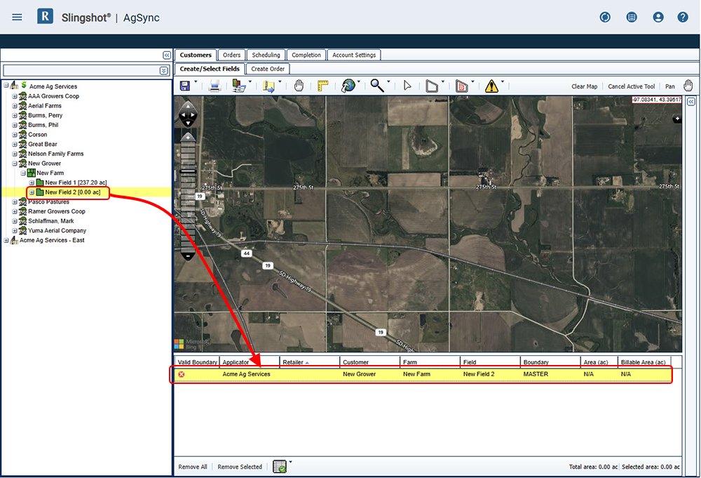
- Use the GFF tree on the left of the page to select the field to which the boundary will be added.
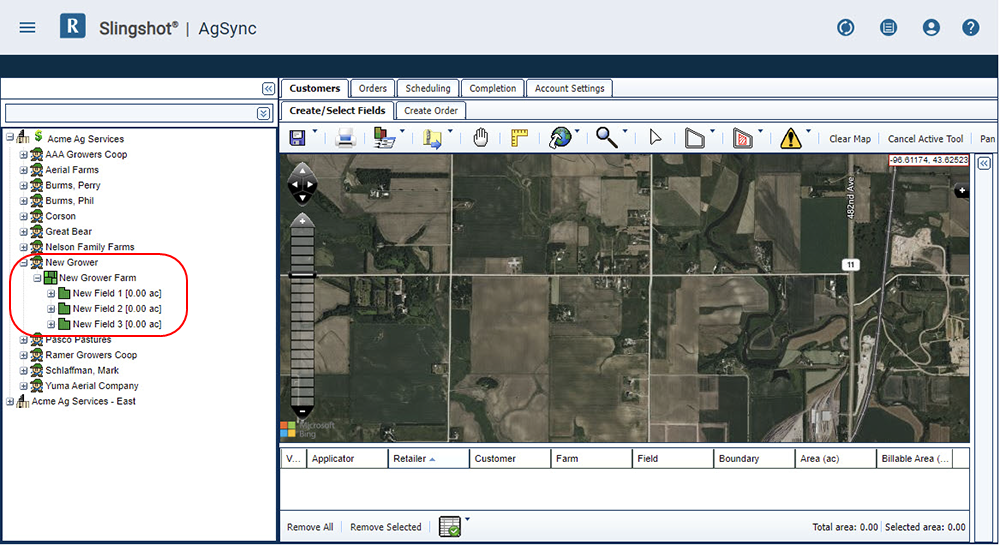
Note: A field without a boundary or zones will display with an area of zero. When added to the working table in subsequent steps, these fields will also display a red x icon in the Valid Boundary column.
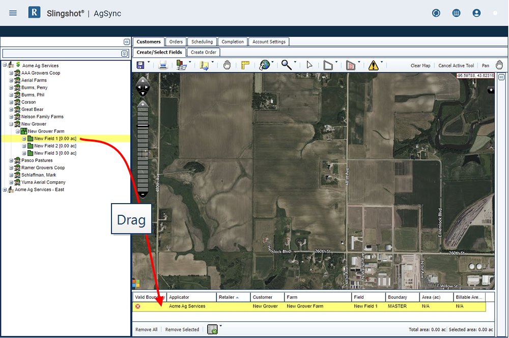
- Drag the selected field to the working table area at the bottom of the page.
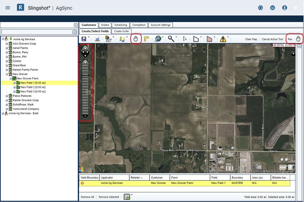
- It is recommended to use the pan and zoom tools to move the map view to the area in which the boundary is to be created.
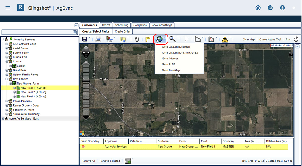
Note: Optionally, use the GoTo button to find a location via latitude-longitude, a street address, PLSS, or township information.
- Next, use one of the following methods to add a boundary to the selected fields.
The draw boundary tool is well suited for creating boundaries for rectangular and straight sided field areas:
- Select the Boundary Tools menu, then New Boundary, and Draw Boundary.

- With the Draw Boundary tool selected, begin clicking on the map to outline the field boundary. Each click creates a point, or vertex, for the boundary. Continue creating as many vertices as necessary to define the field area.
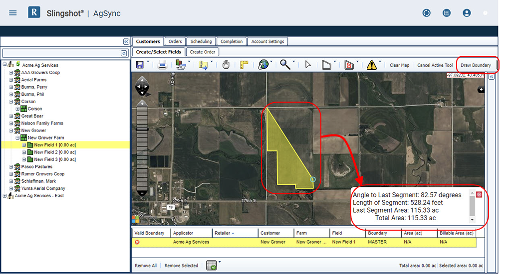
Note: A valid boundary must have a minimum of 3 verticies. AgSync measures segments and area of the created boundaries as vertices are added.
- When the last vertex is place and the boundary is complete, double-click to set the last point. This will set the last point of the boundary and closes the polygon.
Note: The shape will turn red to indicate a closed boundary, but the shape is not yet saved.
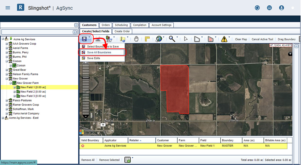
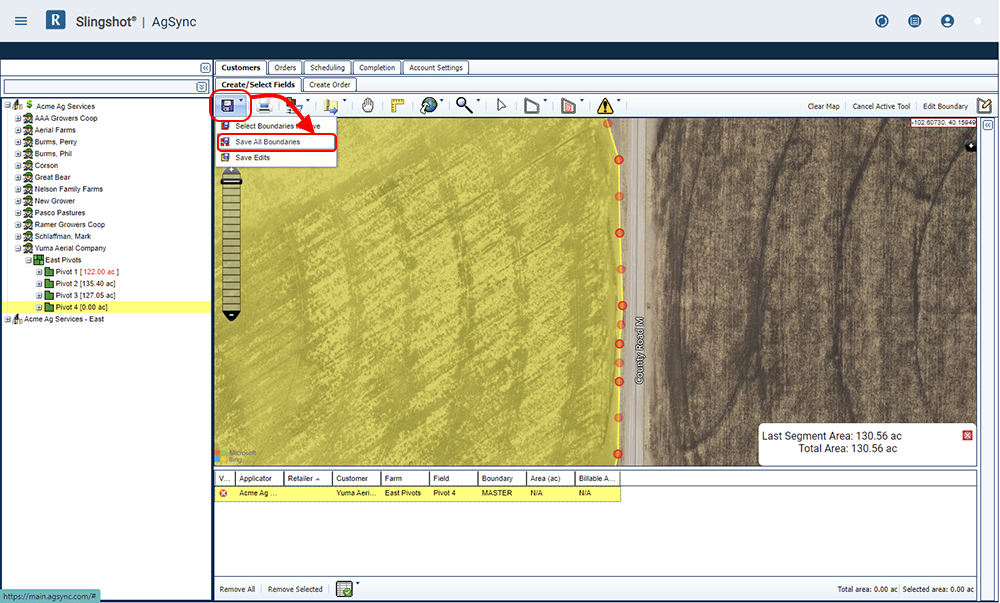
- Select the item in the working table (highlighted yellow) and click Save Boundaries, and Save All Boundaries. The boundary shape will now display in green to indicate that it is saved.
Note: The GFF tree and the Area column in the work area table will now display the area of the boundary.
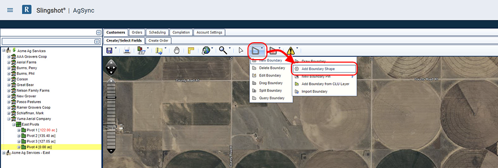
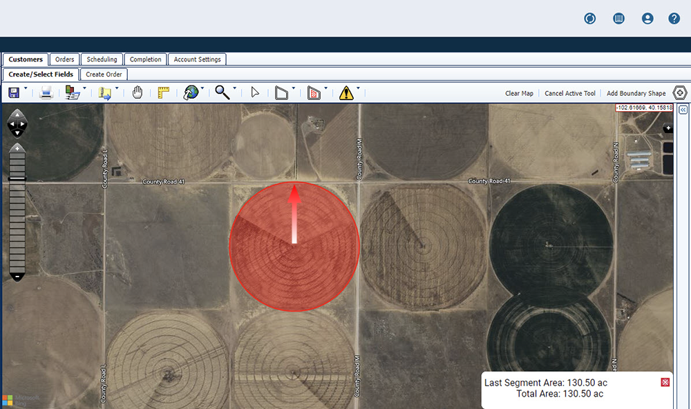
The Boundary Shape tool allows the user to create symmetrical shapes with a minimum of 3 sides. This tool may also be used to create a circular zone for fields such as areas irrigated with center pivots.
- Select the Boundary Tools menu, then New Boundary, and Add Boundary Shape. A prompt will display with the Number of Sides field.
- Enter the number of sides for the shape and select the OK button.
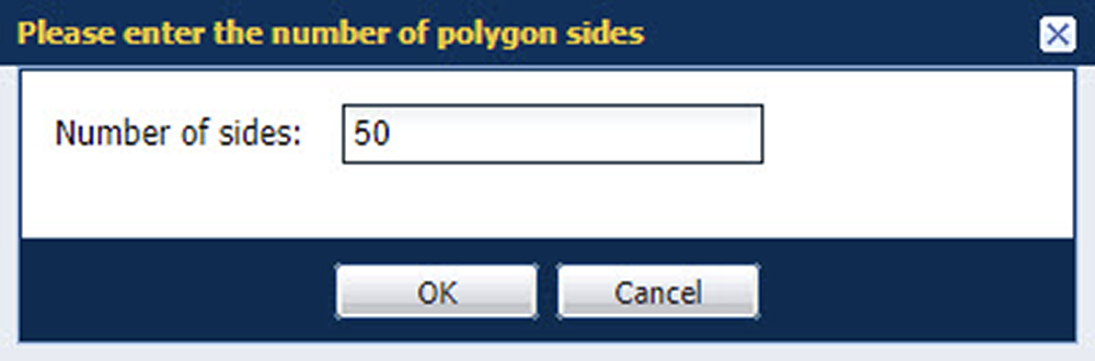
- The shape must have a minimum of 3 sides.
- This tool will always creates a symmetrical shape. To create a circular field area, enter a high value (e.g. 50) for the number of sides.
- To create a boundary shape, click in the center of the field shape and drag outward toward the field edge. Release the mouse button to create the boundary.
- To adjust the created field boundary (e.g. fine-tune the position of the boundary verticies), select the Boundary Tools, and then Edit Boundary.
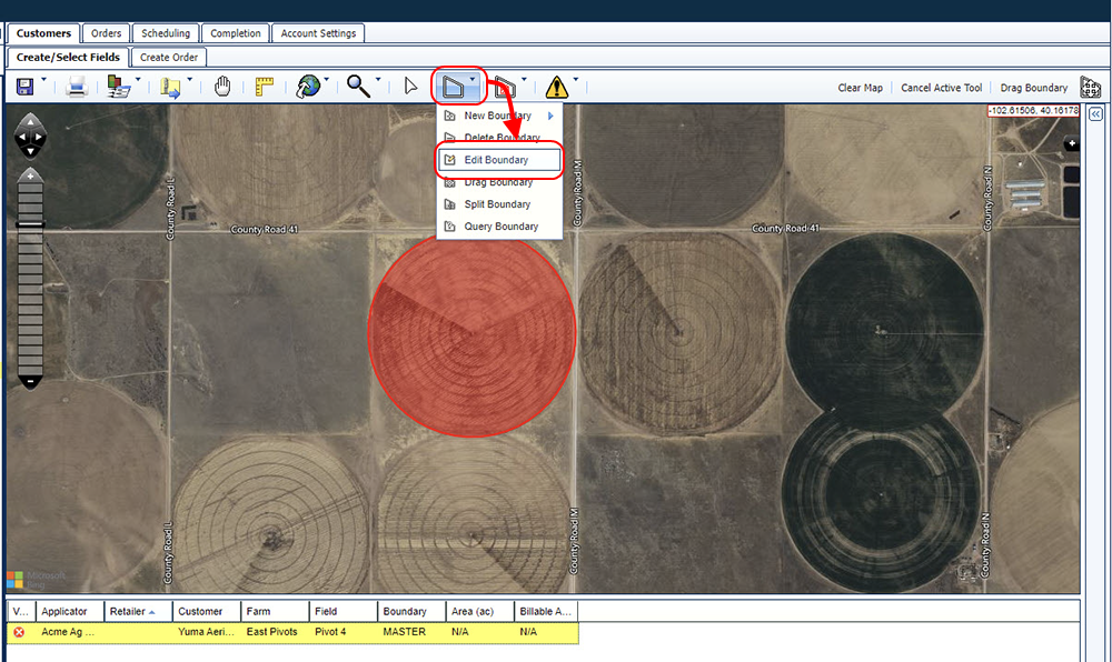
- Select the field shape to edit. The boundary changes to yellow and the boundary verticies are displayed.
- When the boundary is displayed as desired, select the item in the working table (highlighted yellow) and click Save Boundaries, and Save All Boundaries. The boundary shape will now display in green to indicate that it is saved.
Note: The GFF tree and the Area column in the work area table will now display the area of the boundary.
Note: CLU stands for Common Land Unit, which was mapped by the U.S. Department of Agriculture in 2009. If the pre-mapped CLU boundary matches the desired field boundaries, it is possible select the boundary rather than manually drawing boundaries.
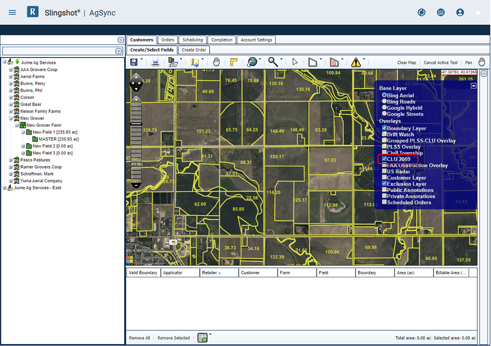
- Begin by creating the new field entry in the GFF tree, then dragging that field name into the working table.
- Select the Boundary Tools menu, then New Boundary, and Add Boundary from CLU Layer. The CLU 2009 map layer will activate.
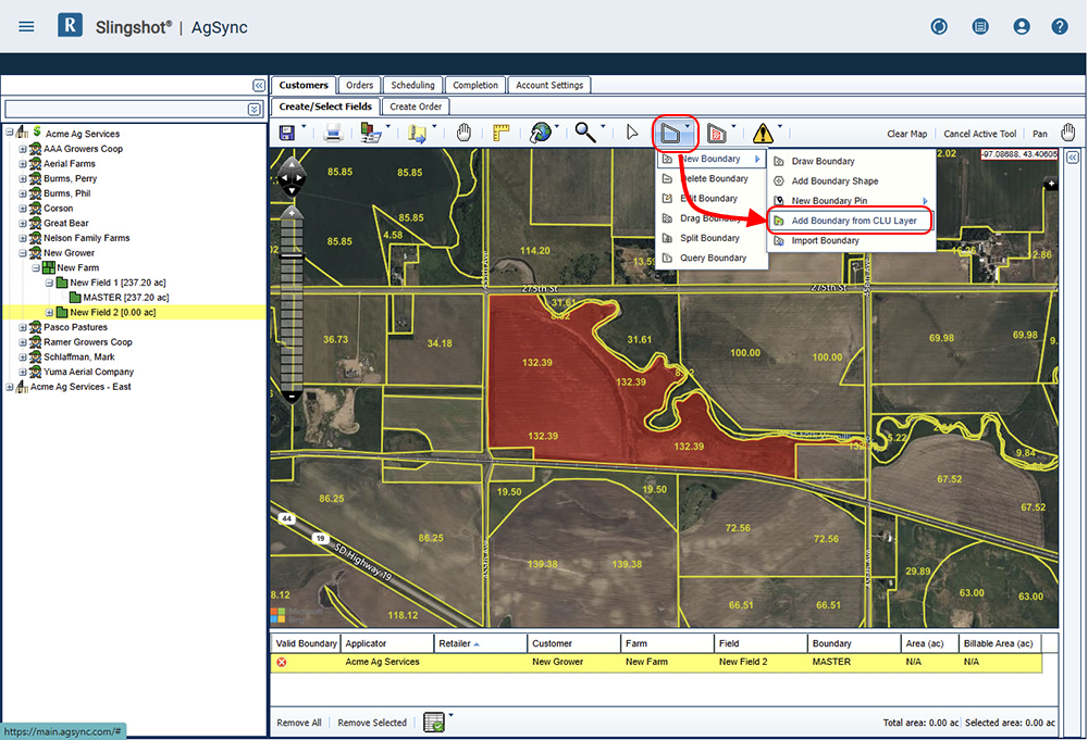
- Click within the boundary to select the boundary (or boundaries) which will make up this field.
- Select the item in the working table (highlighted yellow) and click Save Boundaries, and Save All Boundaries. The boundary shape will now display in green to indicate that it is saved.
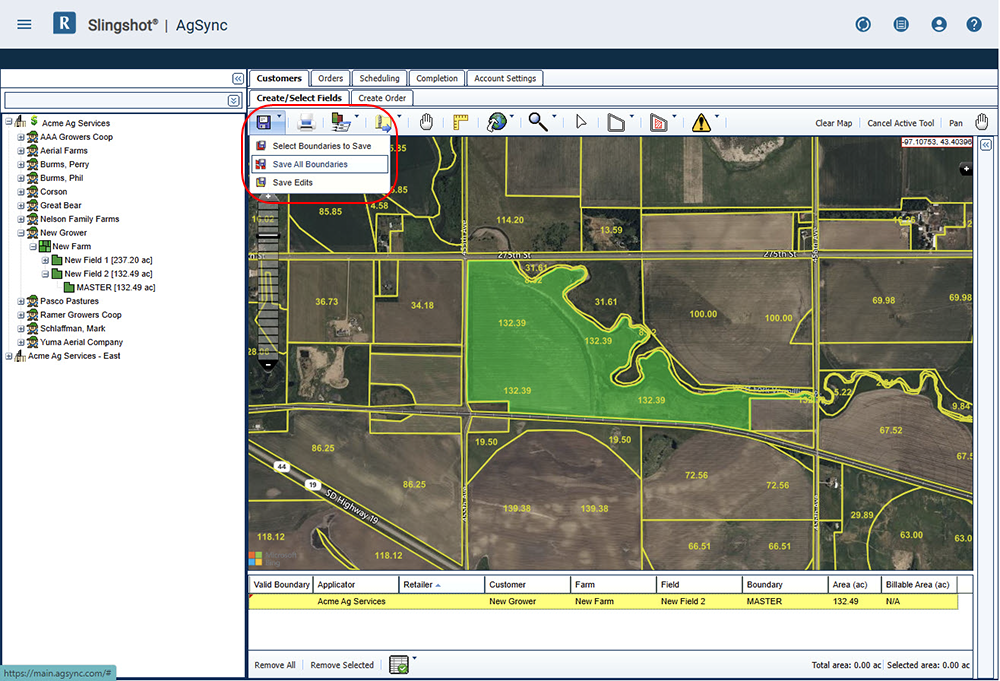
Note: The GFF tree and the Area column in the work area table will now display the area of the boundary.
If you have an existing shapefile![]() A shapefile is a vector format consisting of a .shp, .shx, and .dbf file and is used to store geospacial data and information such as field boundaries, product application coverage, and waypoints., you are able to import that shapefile to create the boundary for a field entry.
A shapefile is a vector format consisting of a .shp, .shx, and .dbf file and is used to store geospacial data and information such as field boundaries, product application coverage, and waypoints., you are able to import that shapefile to create the boundary for a field entry.
- First, drag the field entry into the working table at the bottom of the screen.
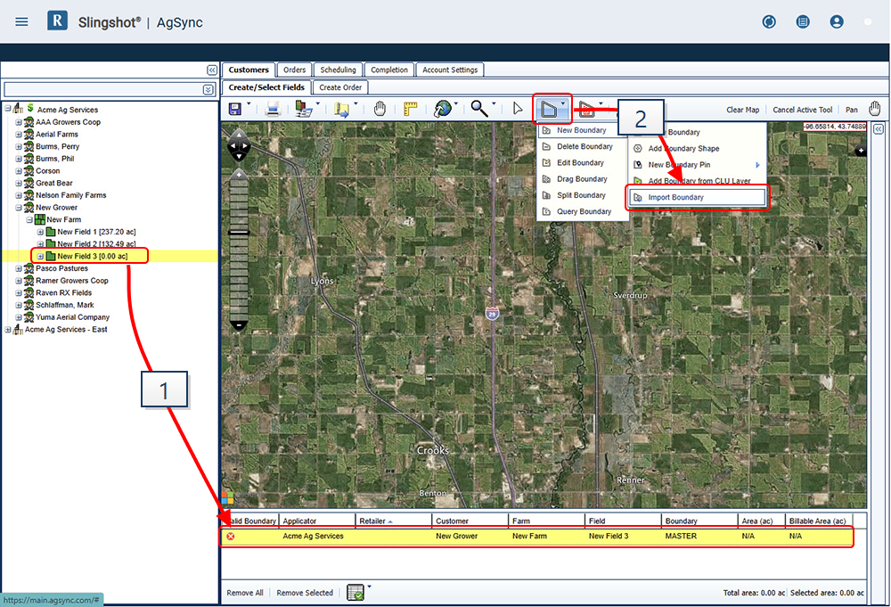
- Select the Boundary Tools menu, then New Boundary, and Import Boundary. The Import Boundary File prompt will display.
- Complete the information on the prompt to complete the Import:
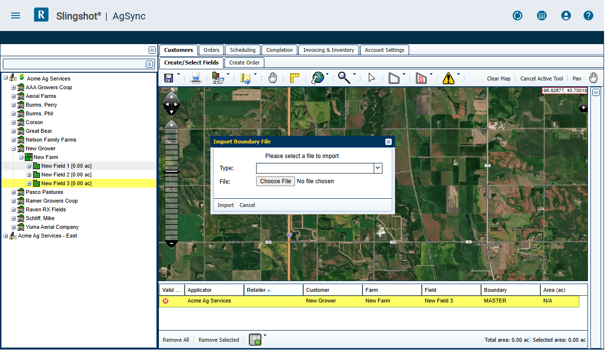
- Type: Select one of the three compatible file types
- Shapefile (.zip)
- KMZ
- KML
- File: Click the Choose File button Navigate and select the existing file you wish to import
- Click the Import button in the lower, left corner of the prompt.
- Type: Select one of the three compatible file types
- If the file is a valid boundary file, the polygon will populate and the map view will zoom to the field location.
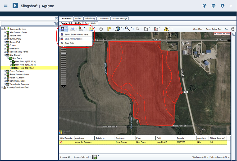
- Select the item in the working table (highlighted yellow) and click Save Boundaries, and Save All Boundaries. The boundary shape will now display in green to indicate that it is saved.
Note: The GFF tree and the Area column in the work area table will now display the area of the boundary.
Last Revised: Jan 2025