Install the Combine Cables
|
|
|
|---|---|
|
|
Use caution while working on the cab roof or standing on exterior surfaces. Surfaces may be uneven or slippery and hardware or harnesses may present tripping hazards. Contact a local equipment dealer for additional information or assistance with working on the roof or from an elevated position on a specific make and model machine. |
- Raven Cart Automation™ System Diagram - Case IH 40 Series Combine
-
Raven Cart Automation™ System Diagram - Case IH 50 Series Combine
-
Route the RS Lite and RCU branch of the Combine Roof Cable (P/N 115-2612-002) to the mounting bracket.
-
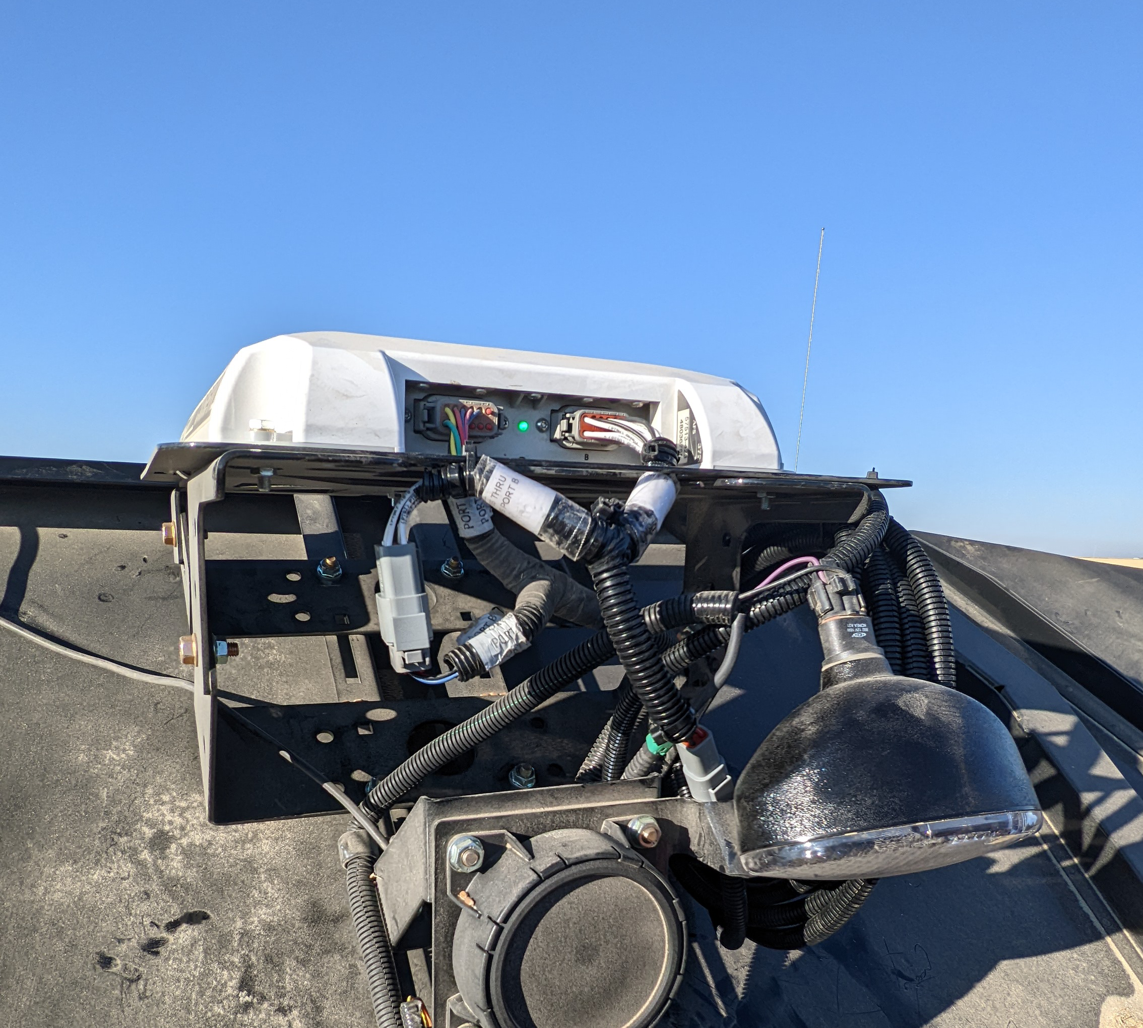
Install the "RS Lite connector" to the RS Lite.
-
Install the "RCU connector" to the RCU.
Note: If not used the "RTK
 Real-time Kinematic"connector will remain capped.
 Note: Port 3 TX signal is sent to the "RTK" and "GPS Port B Pass" through connectors in case position data is needed for another device.
-
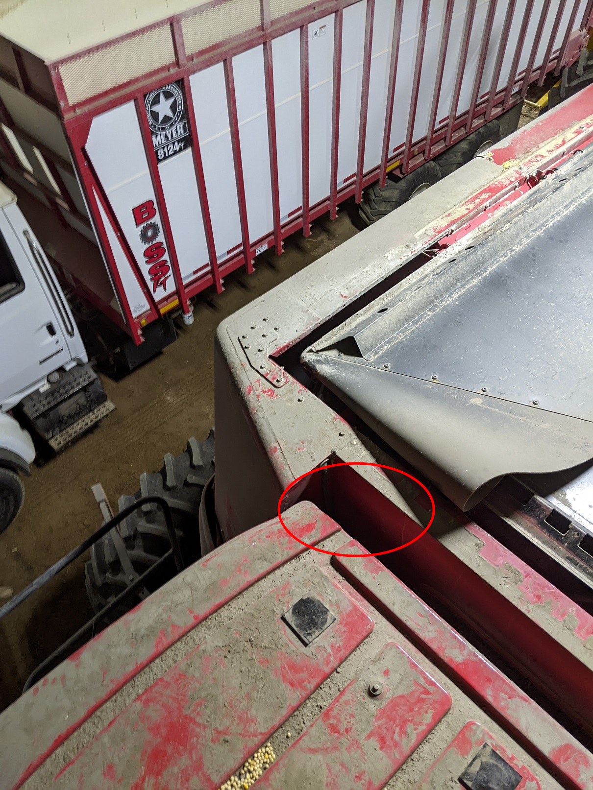
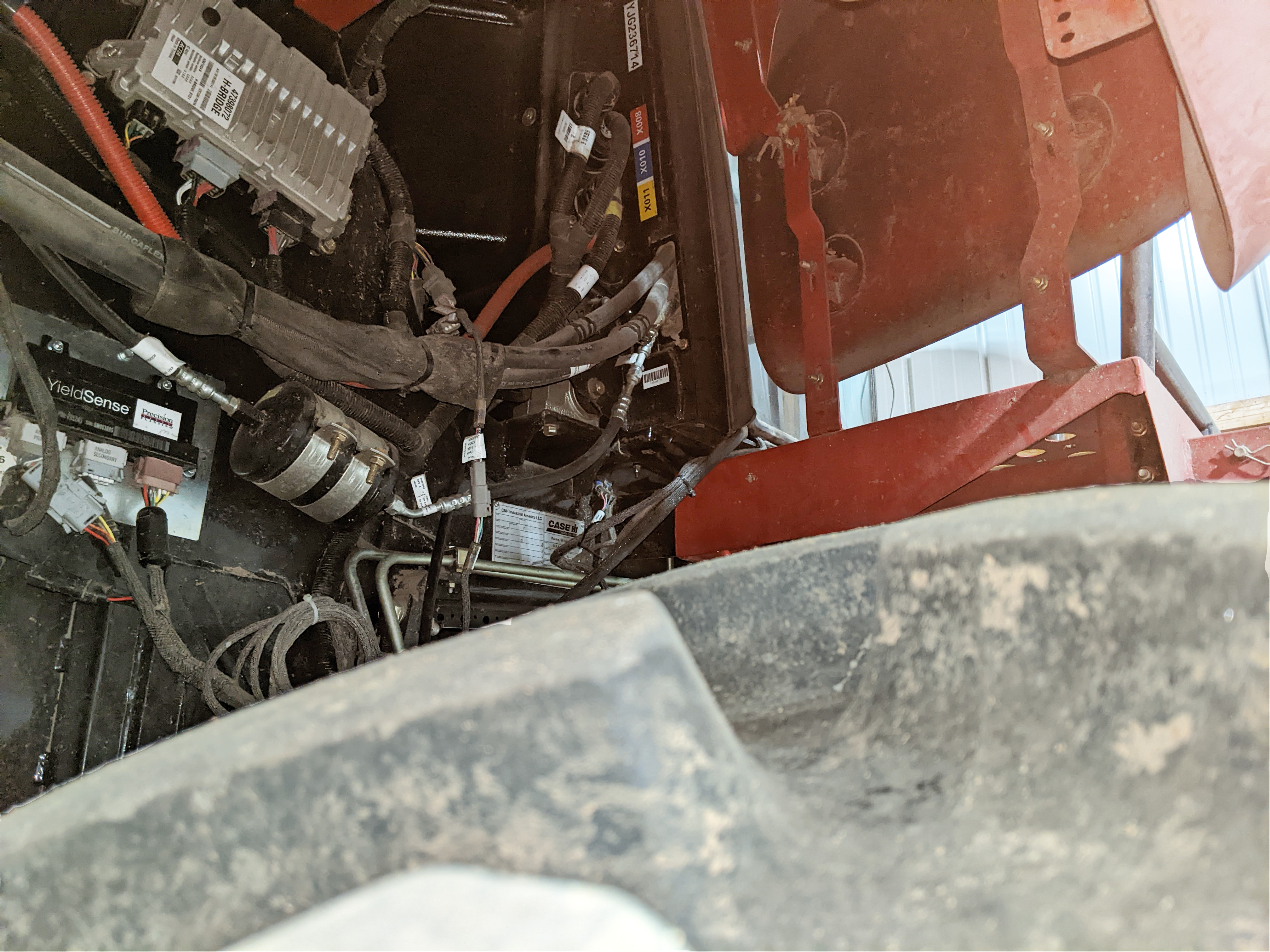
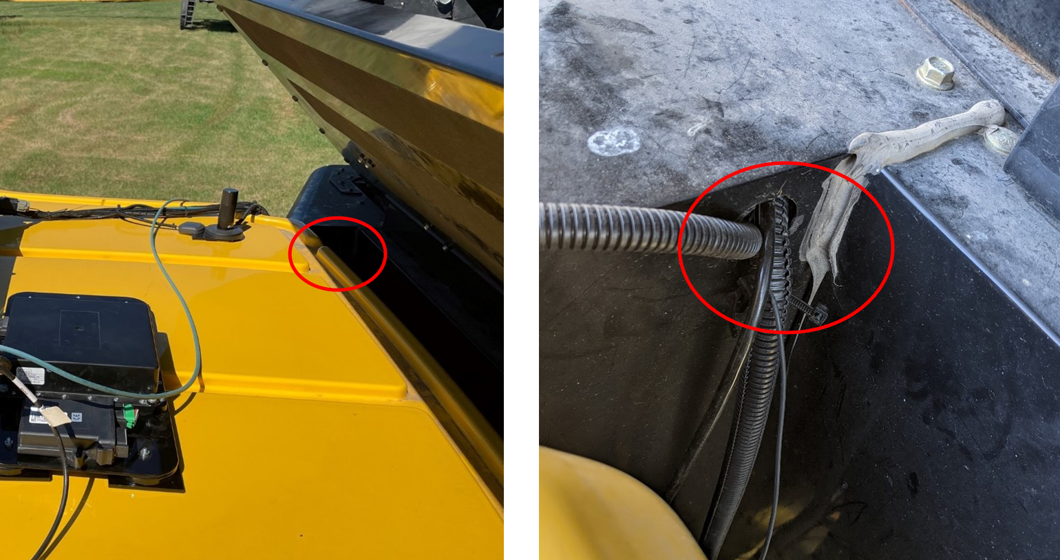
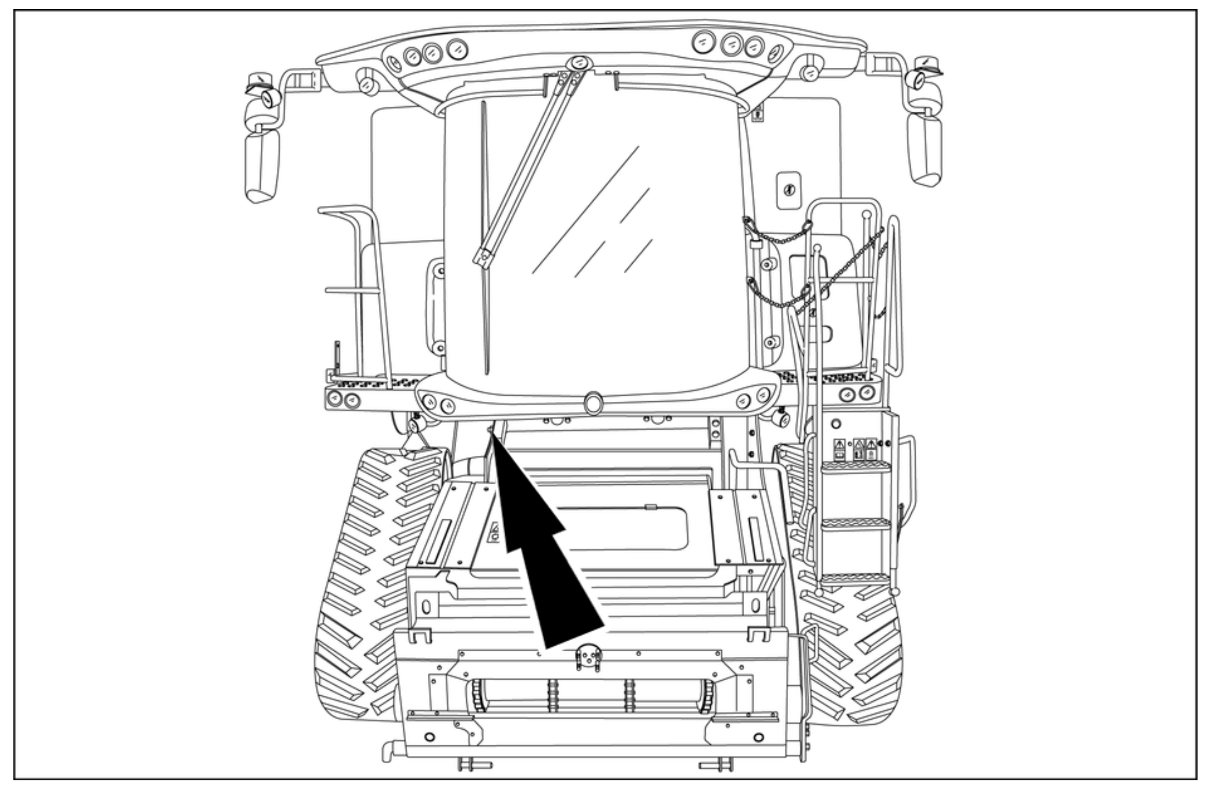
Lower the "X499" and "X010" branch of the Combine Roof Cable through the gap between the cab and grain tank. Install these connectors after the roof components are installed.
-
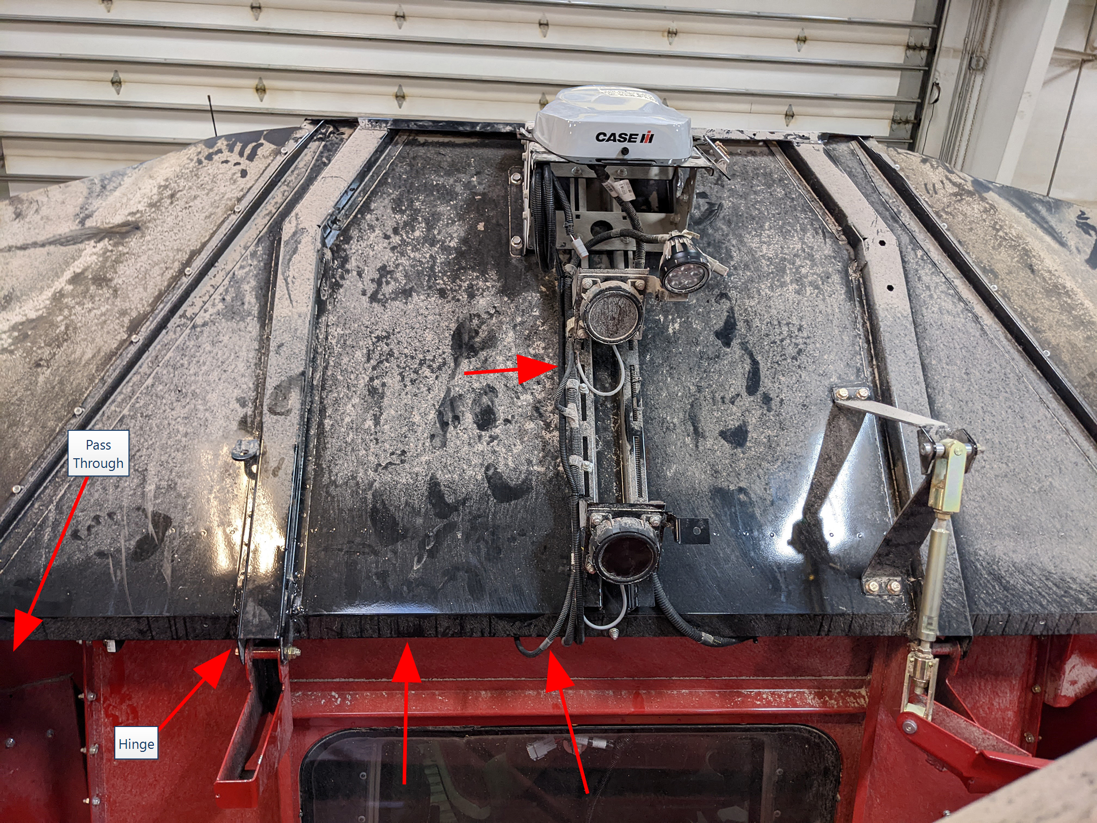
Route the "GPS Port B" branch along the roof towards and through the pass through into the grain tank. The cable can be routed through either side of the grain tank depending on the ease of installation and existing cable routing.
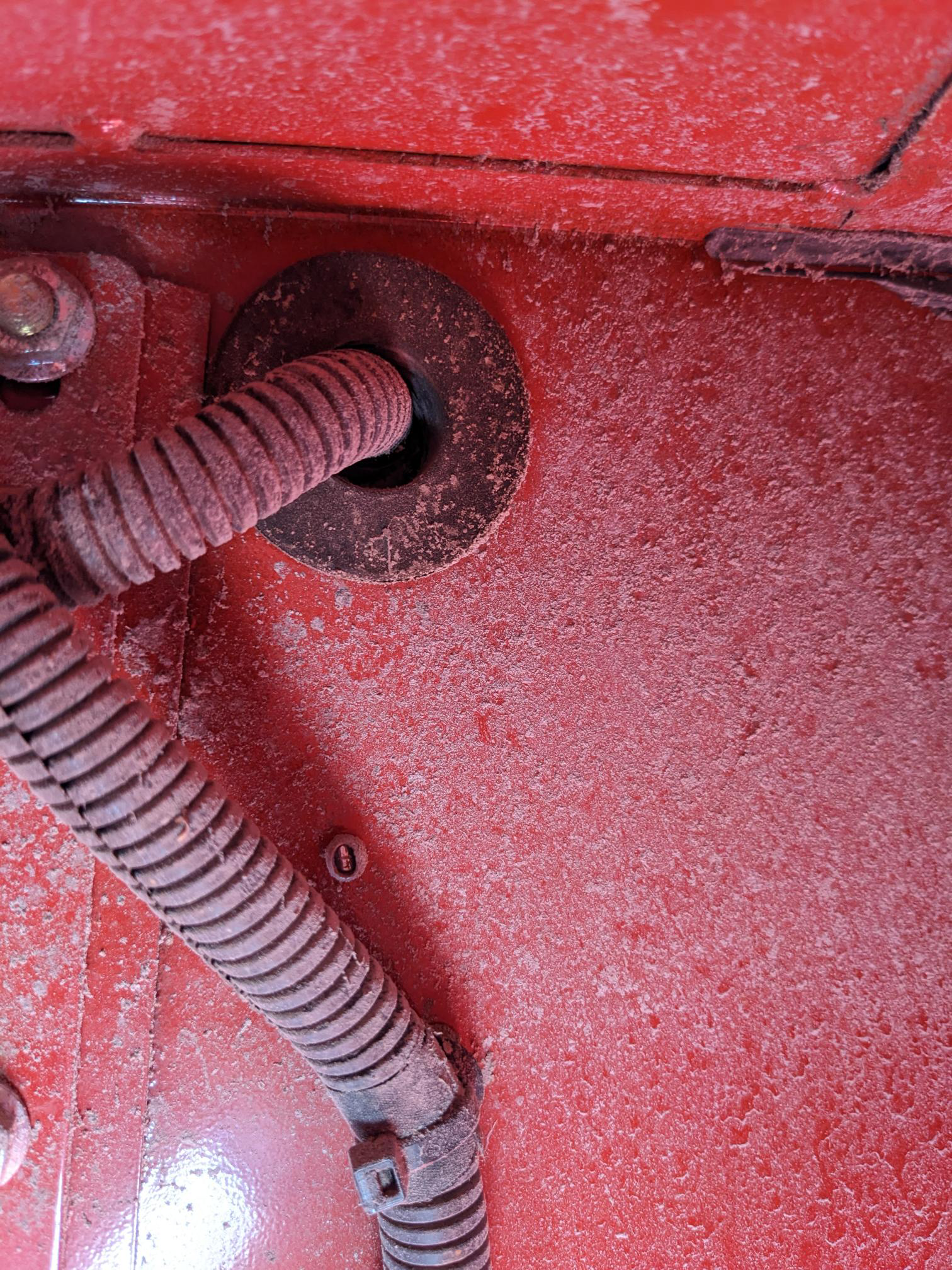
Note: The existing grommet will need to be cut to allow enough space for the cable to pass through or replace the grommet included in the kit. Follow existing cables and avoid potential pinch points.
-
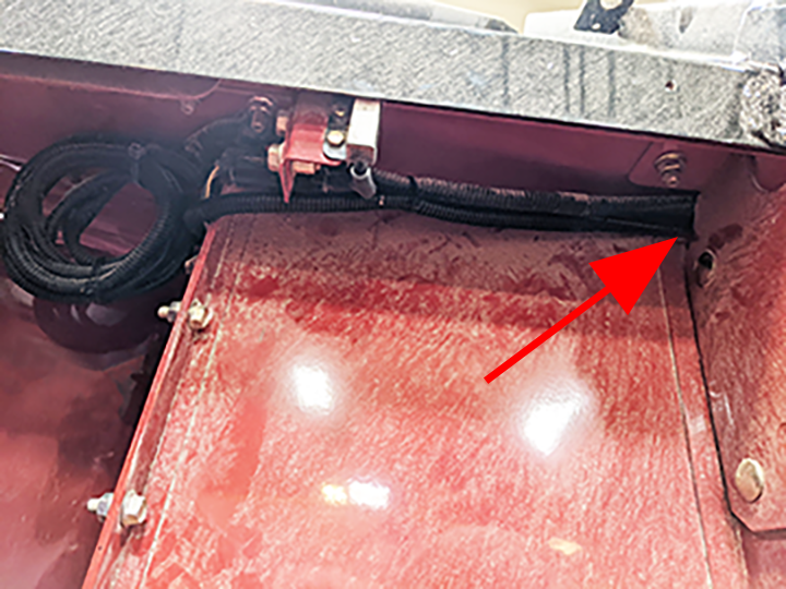
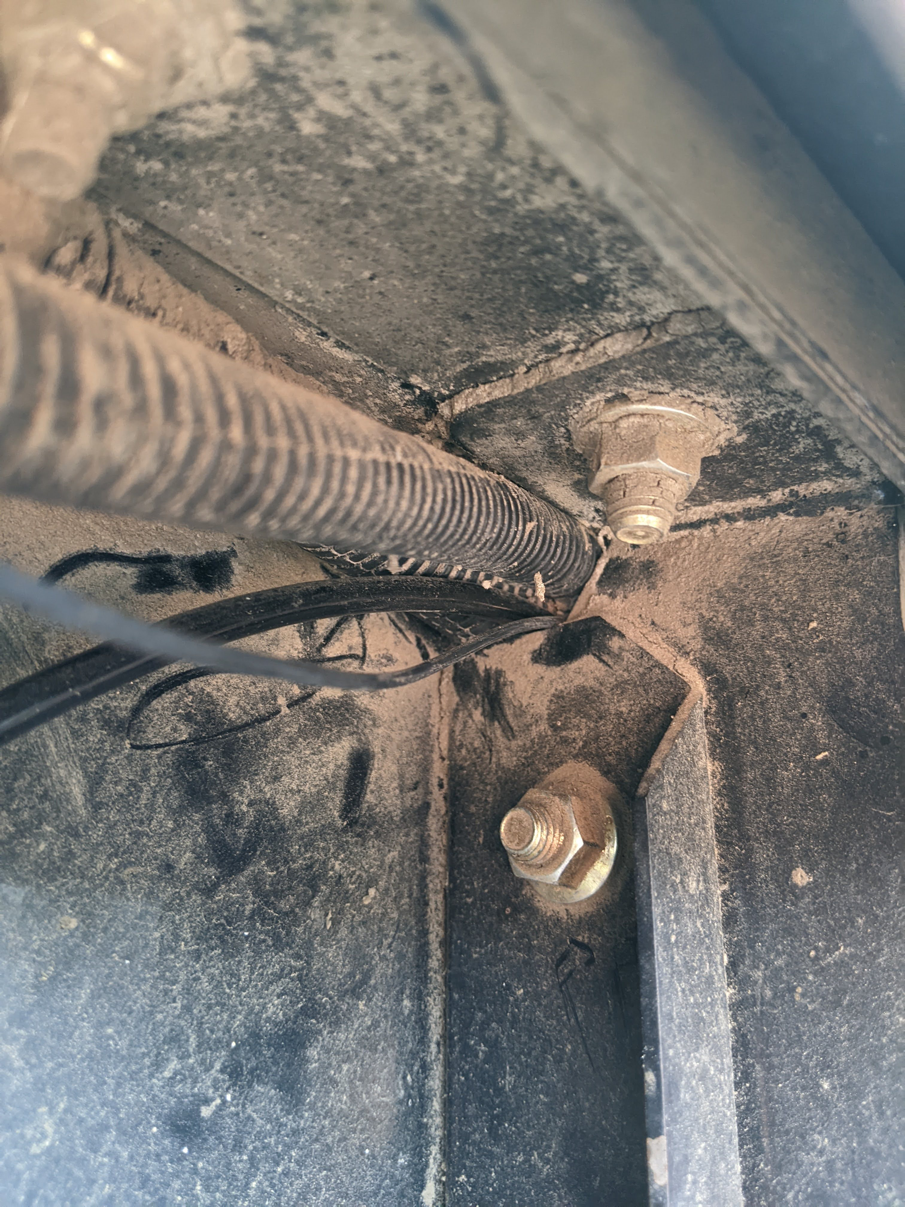
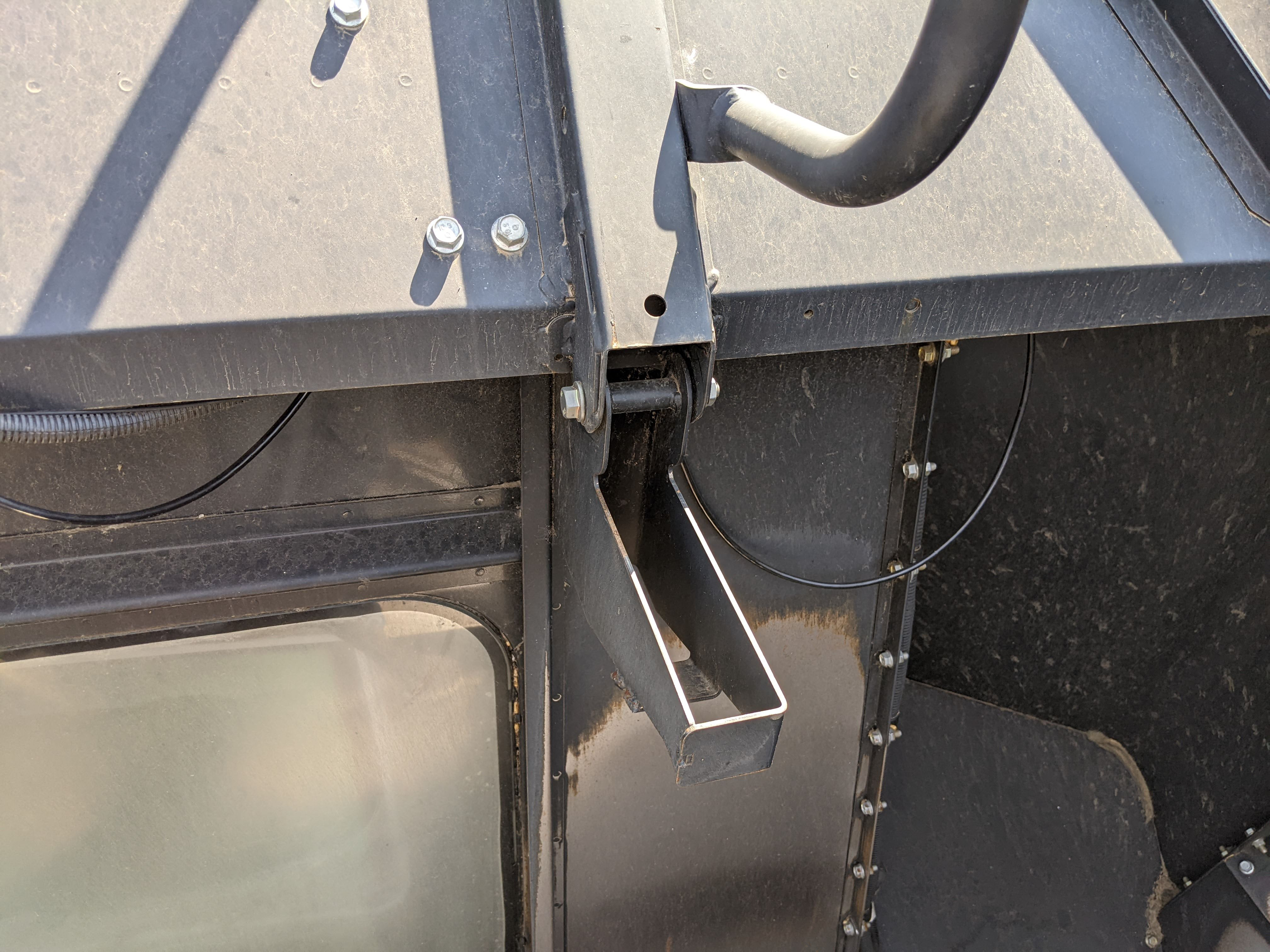
Once the cable is inside the grain tank route it behind the gusset for the grain tank extension hinge and towards the existing cabling up to the receiver.
-
Route the cable up to the receiver.
-
Install the "GPS Port B" connector into port B on the receiver.
Note: If there is another device already connected to port B on the receiver disconnect it and install into the "Pass Thru GPS Port B" connector on the combine cable. Otherwise, the "Pass Thru GPS Port B" connector will remain capped.
-
Use tie straps as needed to secure the cable.
Note: Bundle any excess cable and use tie straps to secure it under the receiver.
-
Ensure all roof cables are properly installed and secured.
-
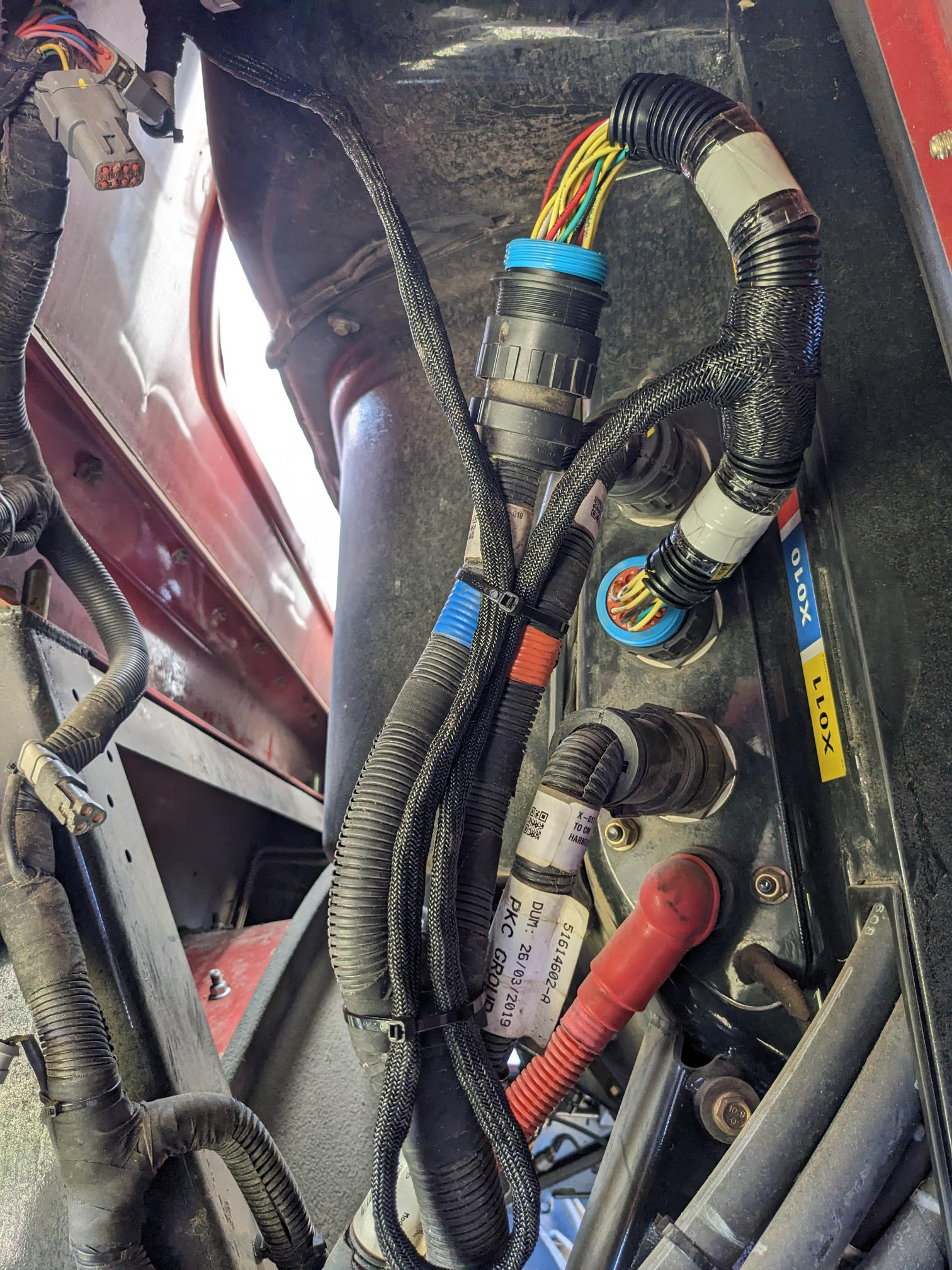
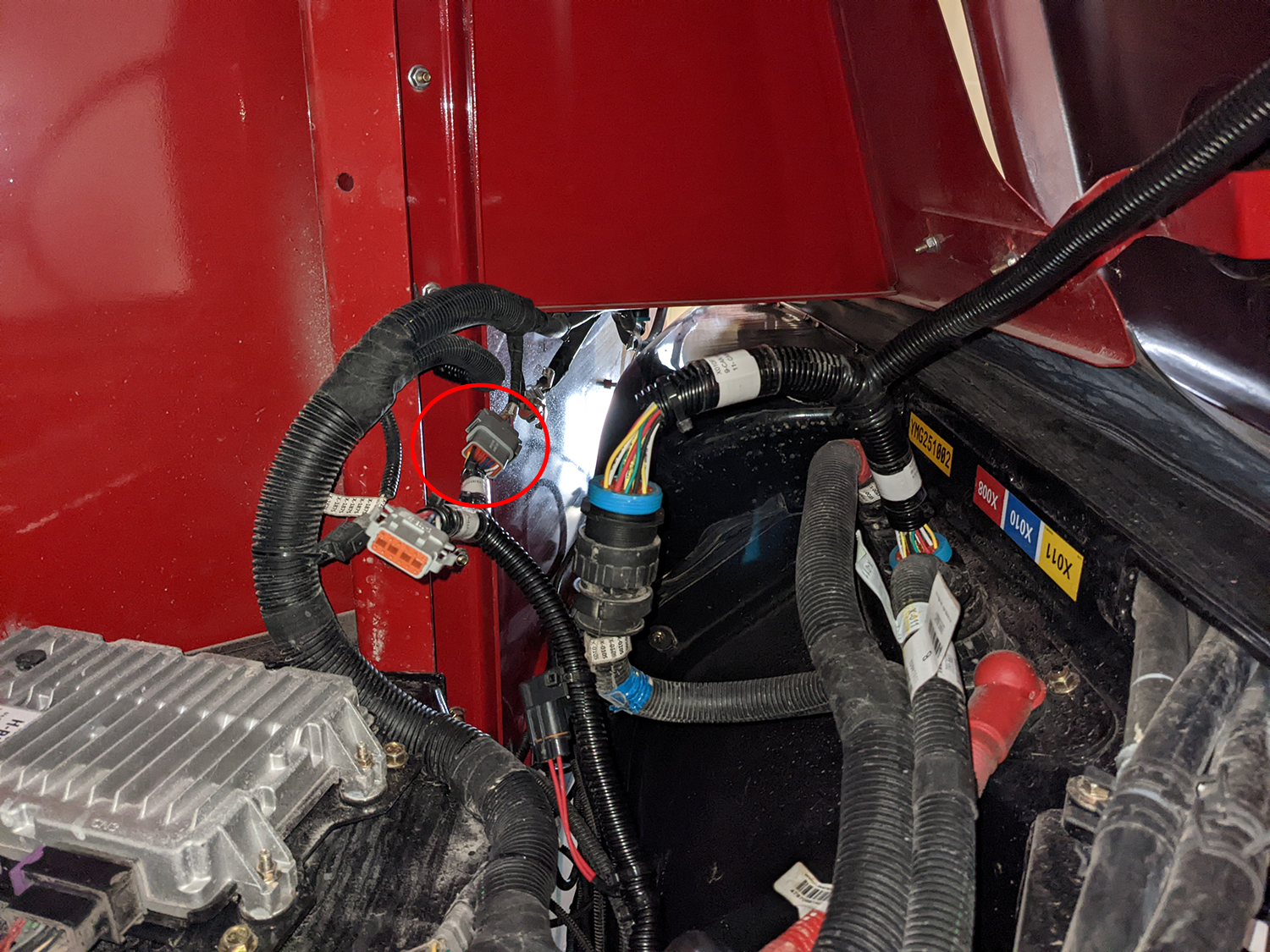
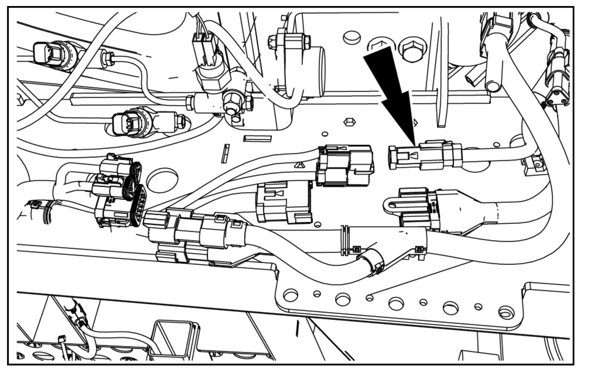
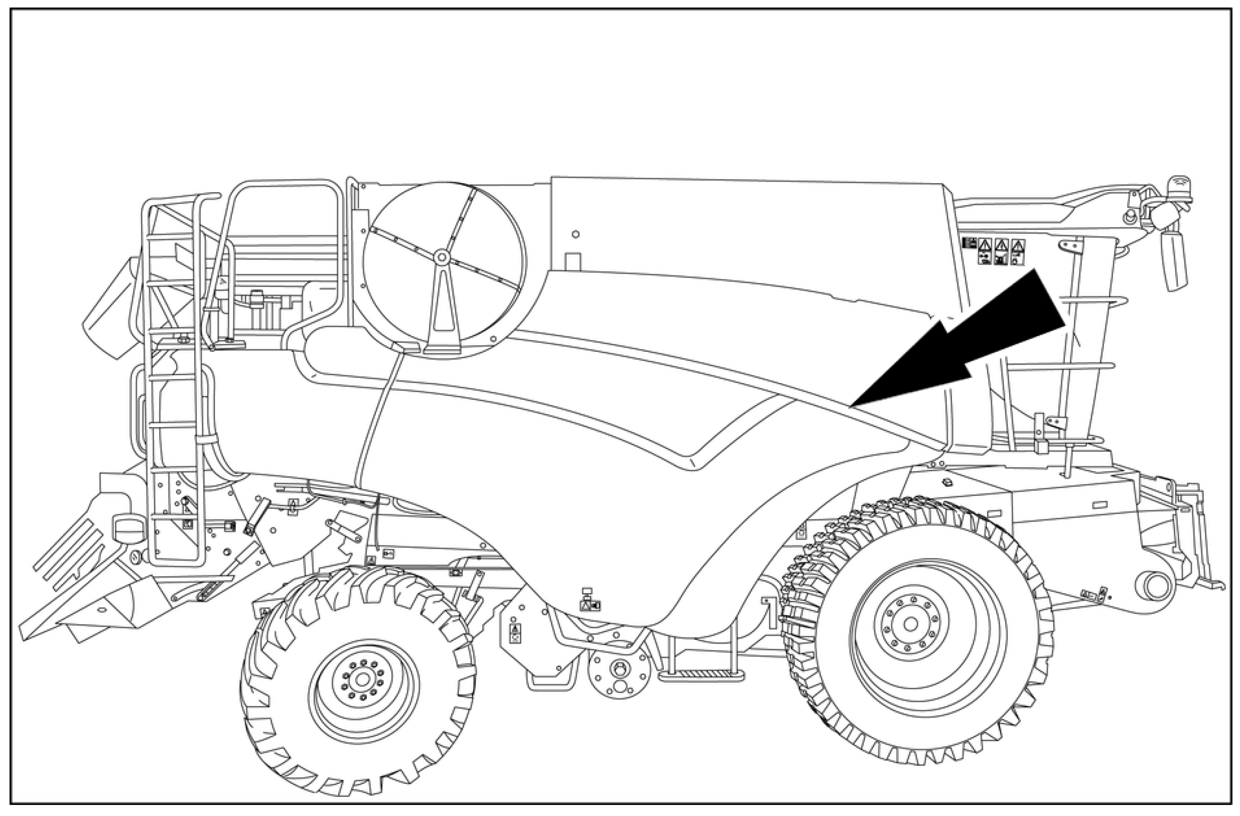
Locate the "X010" and "X499" connectors on the cab above the right front tire.
-
Disconnect the "X010" connector from the bulkhead. Tee into the connector with the corresponding connectors on the combine cable.
-
Follow the harness from the "X010" connector back until you find the "X499" 12-pin DTM connector.
-
Tee into the connector with corresponding connectors on the combine harness.
|
|
|
|---|---|
|
|
Use caution while working on the cab roof or standing on exterior surfaces. Surfaces may be uneven or slippery and hardware or harnesses may present tripping hazards. Contact a local equipment dealer for additional information or assistance with working on the roof or from an elevated position on a specific make and model machine. |
-
Place the Combine Roof Cable (P/N 115-2612-006) on the cab roof.
-
Install the "RS Lite connector" to the RS Lite.
-
Install the "RCU connector" to the RCU.
Note: If not used the "RTK"connector will remain capped.
Note: Port 3 TX signal is sent to the "RTK" and "GPS Port B Pass" through connectors in case position data is needed for another device.
-
Route the cable towards the back right portion of the roof.
-
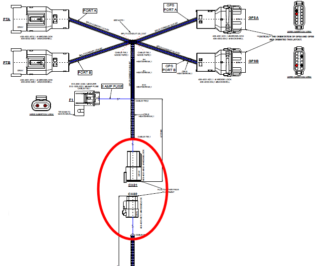
Disconnect the Port A and Port B section of the roof cable at the 6-pin DTM connection.
Note: This section of cable needs to be disconnected in order for it to be routed through the grain tank cutout.
-
Route the 6-pin DTM plug through the cutout and grommet located directly behind the back right section of the cab roof and into the grain tank. The factory grommet can be replaced with a split grommet (P/N 315-0000-032) if necessary.
-
The routing of the factory cabling up to the receiver can be replicated. The 6-pin DTM connector should be routed through the cutout on the gusset in the grain tank.
If it is not possible to route the 6-pin DTM connector through the gusset cutout the alternative is to route it under the gusset and secure it with a zip tie.
-
Route the cable up to the receiver.
-
Reinstall the Port A and Port B section of the roof cable that was previously removed at the 6-pin DTM connection.
-
Remove the 12-pin DTM connector from Port A of the receiver and connect it into the "Port A" receptacle on the roof harness.
-
Connect the "GPS Port A" connector from the roof cable into the open Port A connection on the receiver.
-
If Port B on the receiver is open, connect the "GPS Port B" connector from the roof cable into this connector and leave the dust cap on the "Port B" receptacle of the roof cable.
-
If Port B on the receiver is being used, remove the connector and install into the "Port B"receptacle on the roof cable. The dust cap can be discarded.
-
Connect the "GPS Port B" connector on the roof cable into Port B on the receiver.
-
Use tie straps as needed to secure the cable.
-
Ensure all roof cables are properly installed and secured before leaving the roof.
Locate the CAN Bus Connection
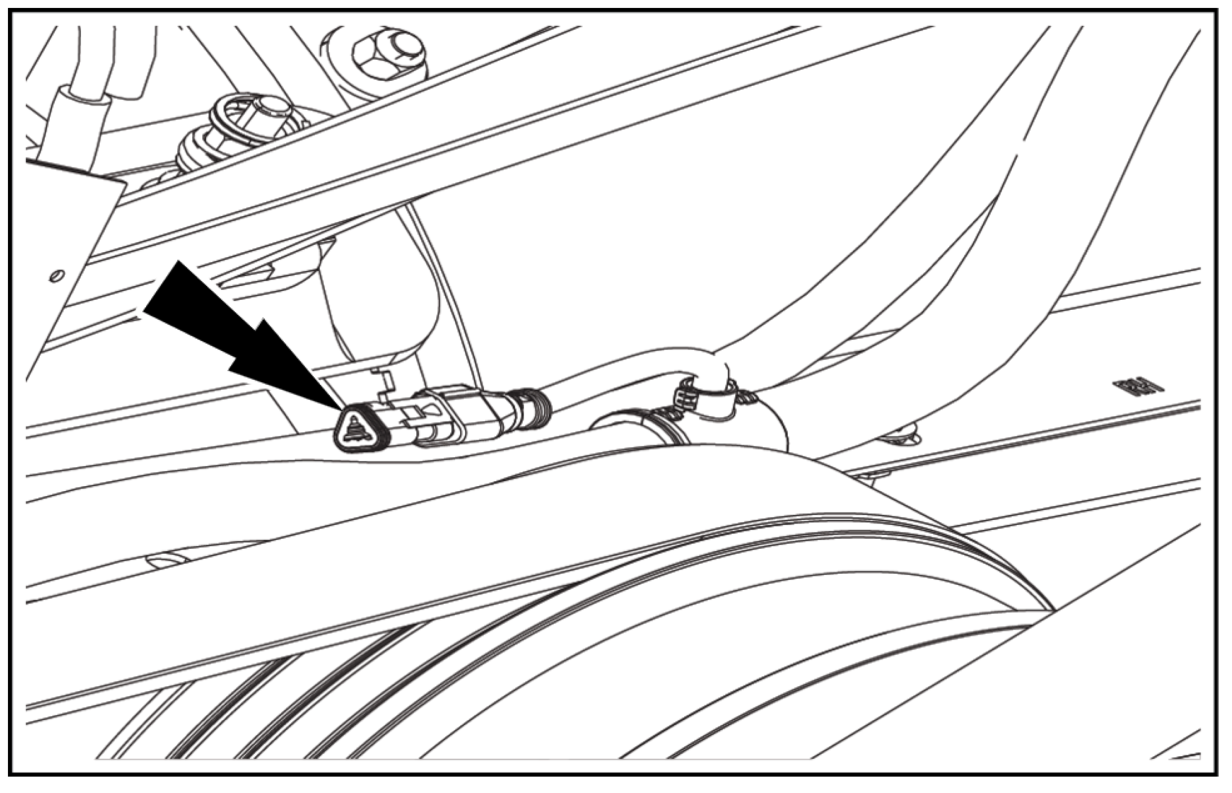
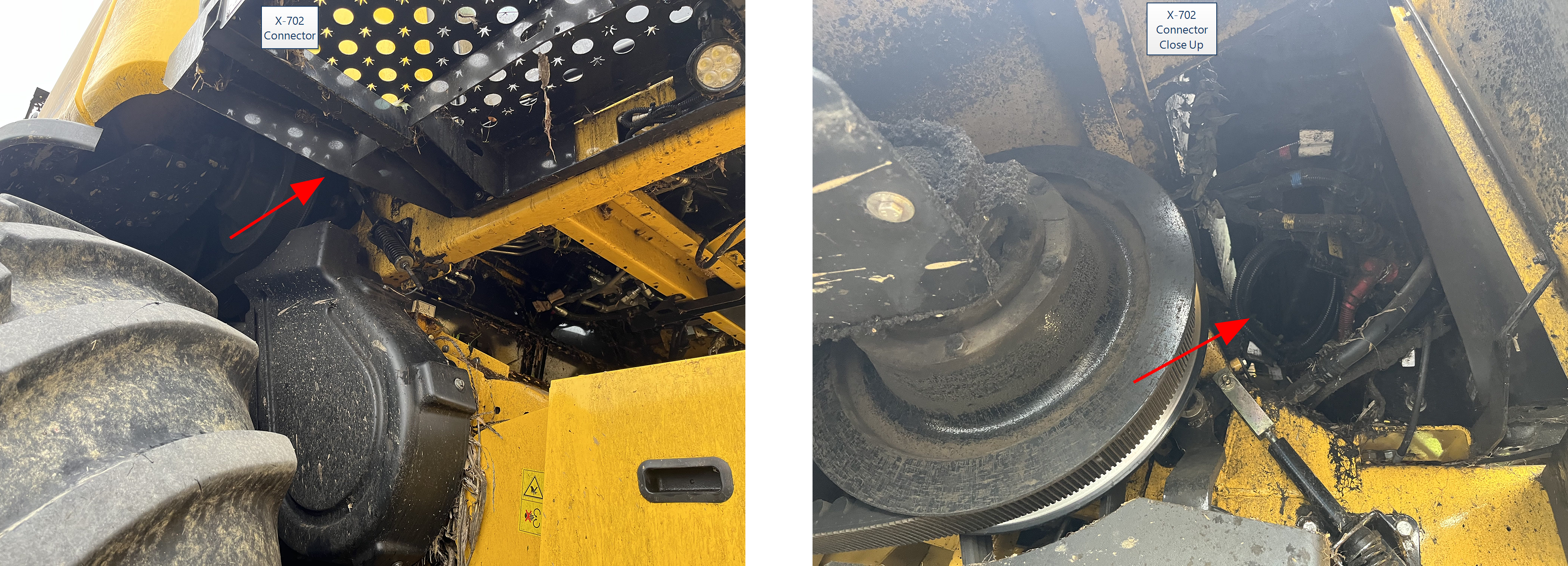
Locate the X-702 connector. There are three possible locations depending on the machine configuration. The most common is on the bottom right side of the cab.
Note: MY24 machines may have a 2-pin terminator at location X-702. If that is the case, depopulate the exiting 3-pin DT plug connector and change to a 2-pin DT plug with pin A becoming pin 1 and pin B becoming pin 2.
Bottom Right Side of the Cab
Right Side of the Machine above the Front Right Tire
Back Right Side of the Cab
The easiest way to find this location is to stand behind the front right tire and look for the row of three bulkhead connectors.
Connect to the Combine CAN Bus
-
Route the X-702P and X702R section of the roof harness between the grain tank and cab down to the X-702 connector.
-
There are two options for how to tie into the combine CAN Bus depending on how the machine is configured.
-
If the X-702 connector is plugged into the X-702A connector, break this connection and plug the X-702R and X-702P connectors from the roof cable into each of these new open machine connections. In this scenario, we are looping the CAN Bus up to our ECUs and back, so no termination is needed within our cable.
-
If the X-702 connector has a terminator plugged into it, remove the terminator and plug the terminator into the X-702P connector. Then plug the X-702R connector from the roof cable into the now open X-702 machine connection. In this scenario, we are extending the main trunk of the CAN Bus and need to terminate it.
-
Last Revised: Mar 2025
 warning